TuneRS Mall Logo
We’re expanding our online store!
We’re improving our website and adding new parts daily.
Can’t find a part or need help with an order? Contact us—we’re happy to help.
← All installation guides

TuneRS technical resources

Transmission Oil Cooler

Illustrated cooler mounting, bracket locations, hose routing and pump connections.

Spec Boxster / Spec Cayman8 steps
Before you begin

The original guide uses annotated photographs. Each section below retains those sheets, including hose labels, bracket locations and measurements. Enlarge the sheets to read the annotations.

Installation steps

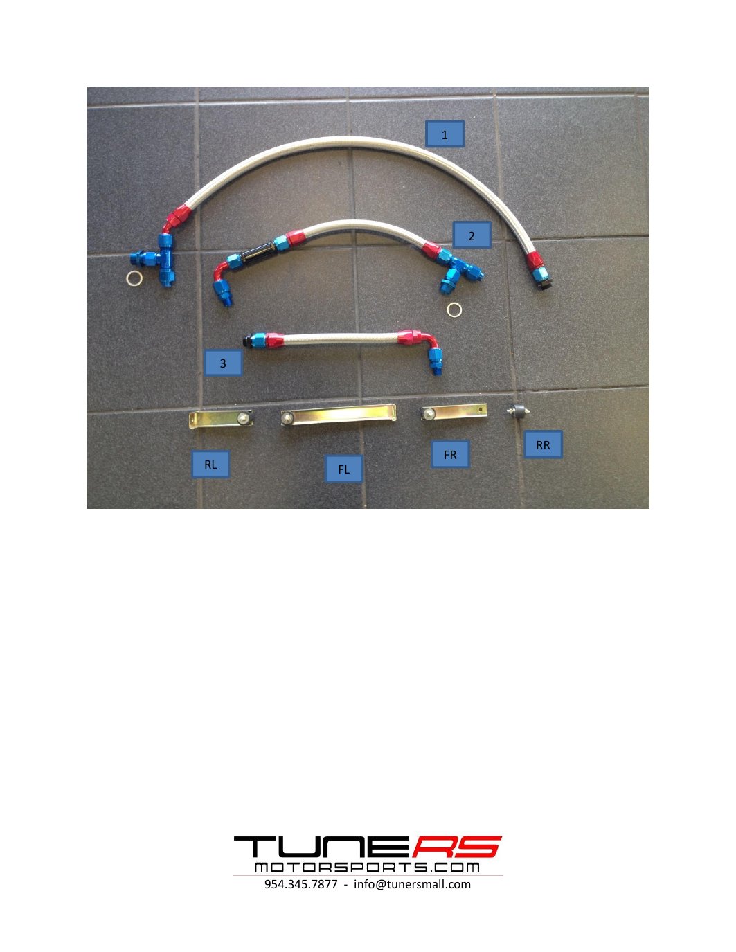
1Step 1Cooler, brackets and connection labels

TRS TRANSMISSION COOLER INSTALLATION GUIDE
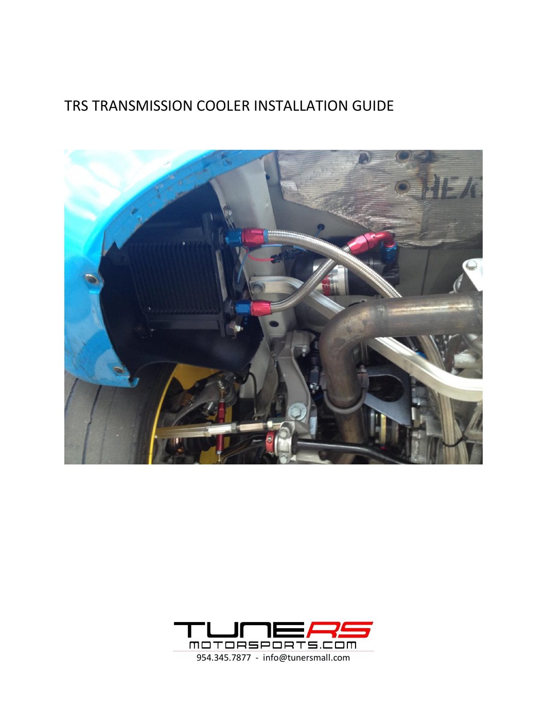
Original instruction sheet, page 1
Original instruction sheet — page 1. Select the image to enlarge.

1

2

3

RR FR RL FL

Original instruction sheet, page 2
Original instruction sheet — page 2. Select the image to enlarge.
2Step 2Mount the cooler on the rear left side

USING PROVIDED BRACKETS, INSTALL COOLER ON THE REAR LEFT SIDE OF VEHICLE AS SHOWN IN PICTURE BELOW

1

RR

3

RL

FR
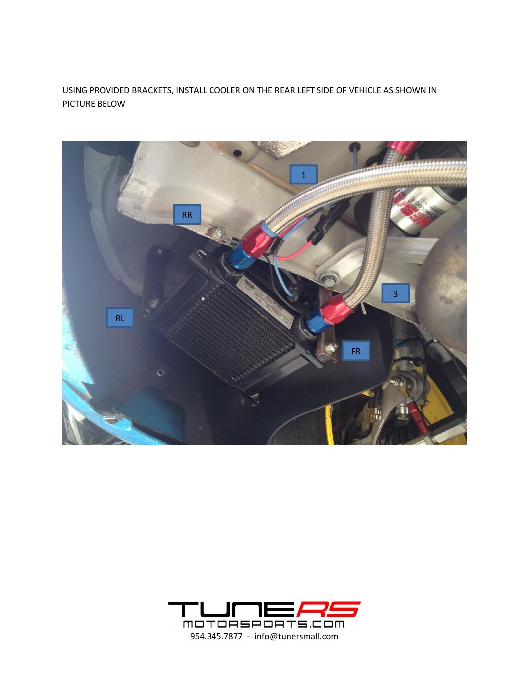
Original instruction sheet, page 3
Original instruction sheet — page 3. Select the image to enlarge.
3Step 3Rear-right bracket position

INSTALL (RR) REAR RIGHT BRACKET 4 INCHES FROM REAR EDGE OF VEHICLE
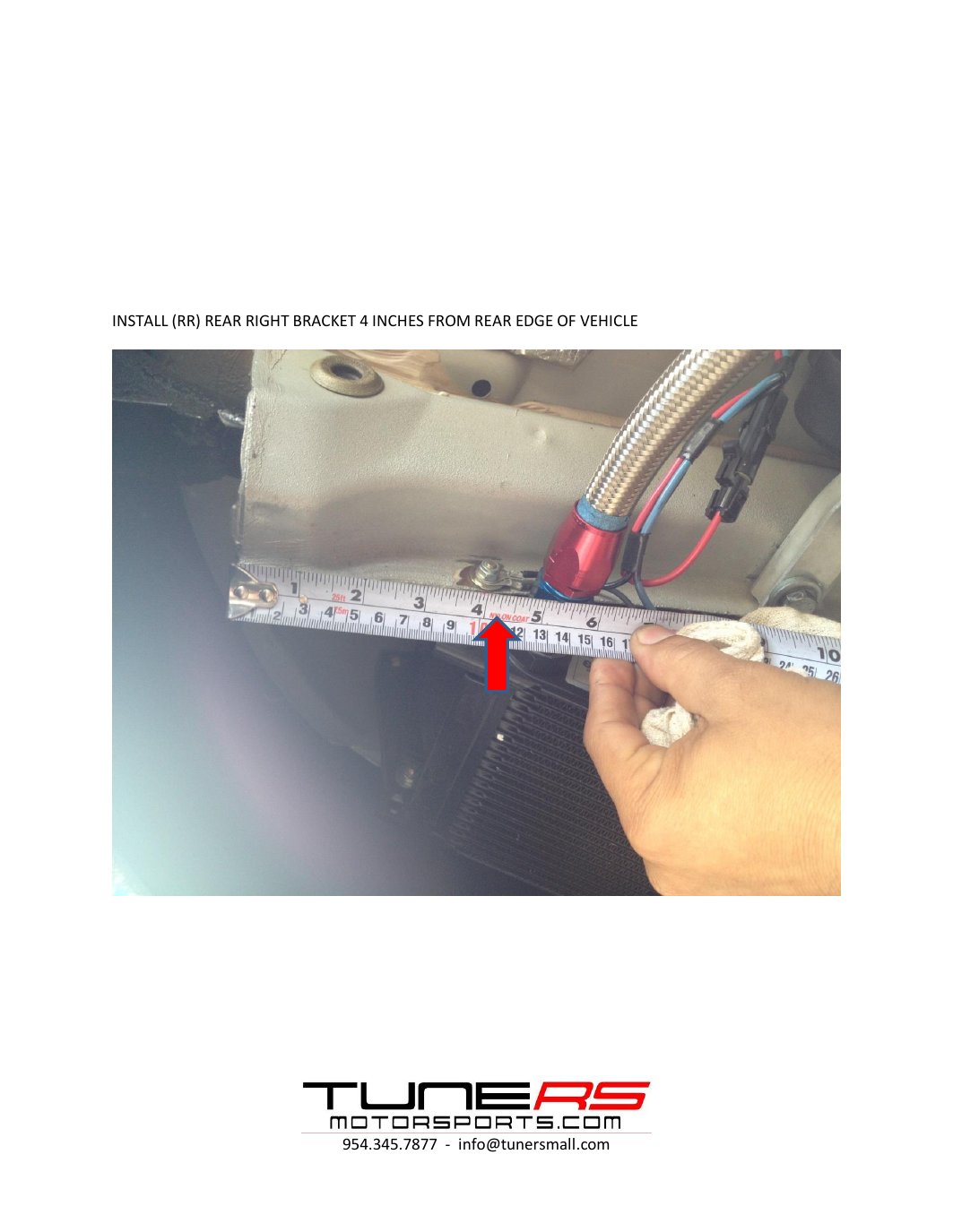
Original instruction sheet, page 4
Original instruction sheet — page 4. Select the image to enlarge.
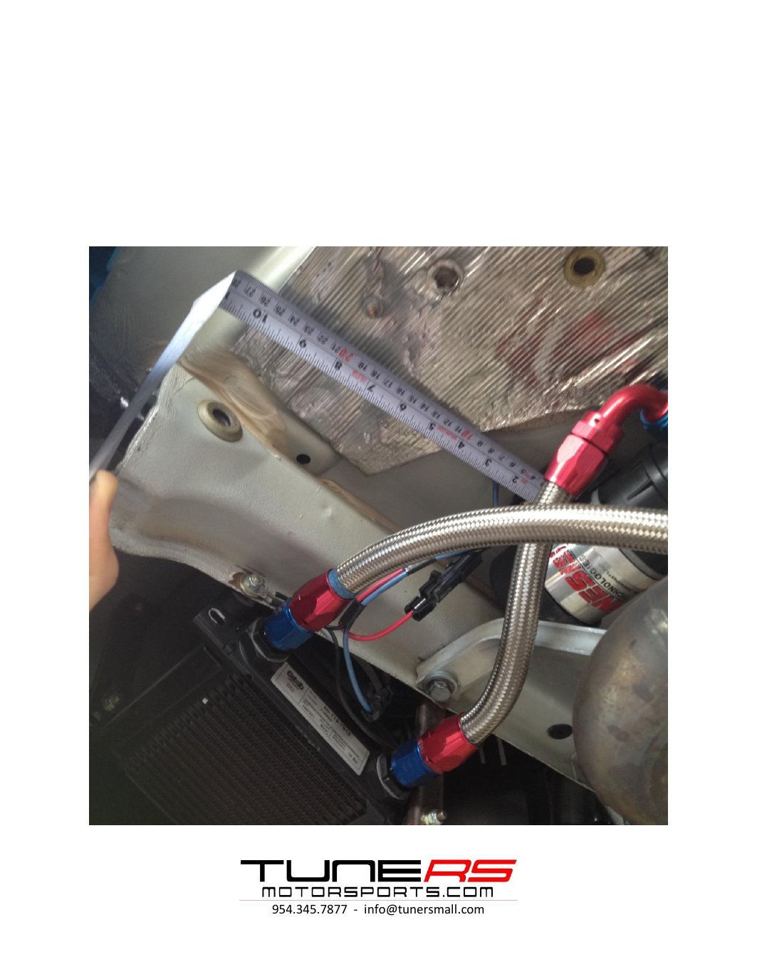
4Step 4Bracket measurements and mounting views

9.5 INCHES FROM REAR EDGE OF VEHICLE
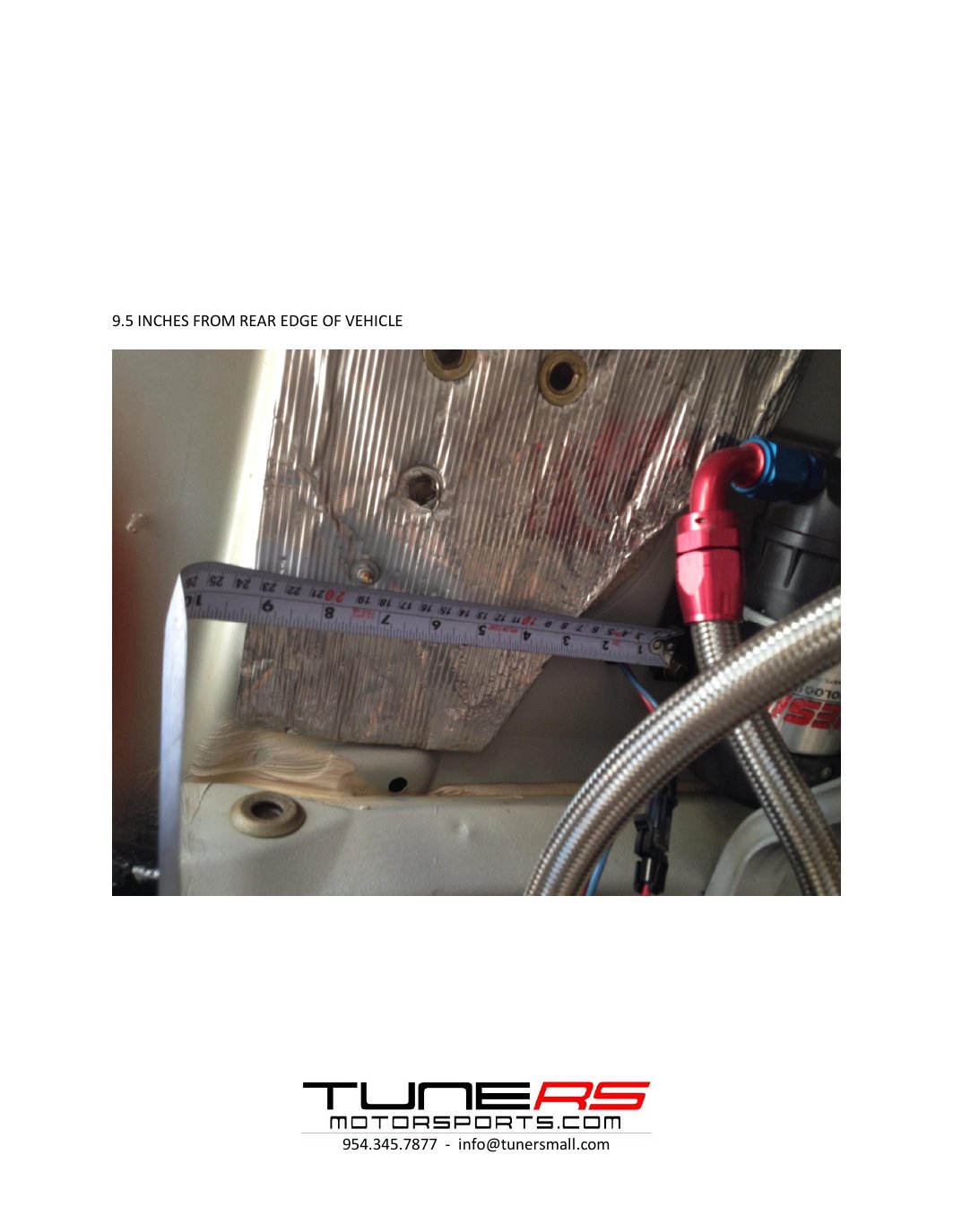
Original instruction sheet, page 5
Original instruction sheet — page 5. Select the image to enlarge.
Original instruction sheet, page 6
Original instruction sheet — page 6. Select the image to enlarge.
Original instruction sheet, page 7
Original instruction sheet — page 7. Select the image to enlarge.
5Step 5Transmission drain to cooler

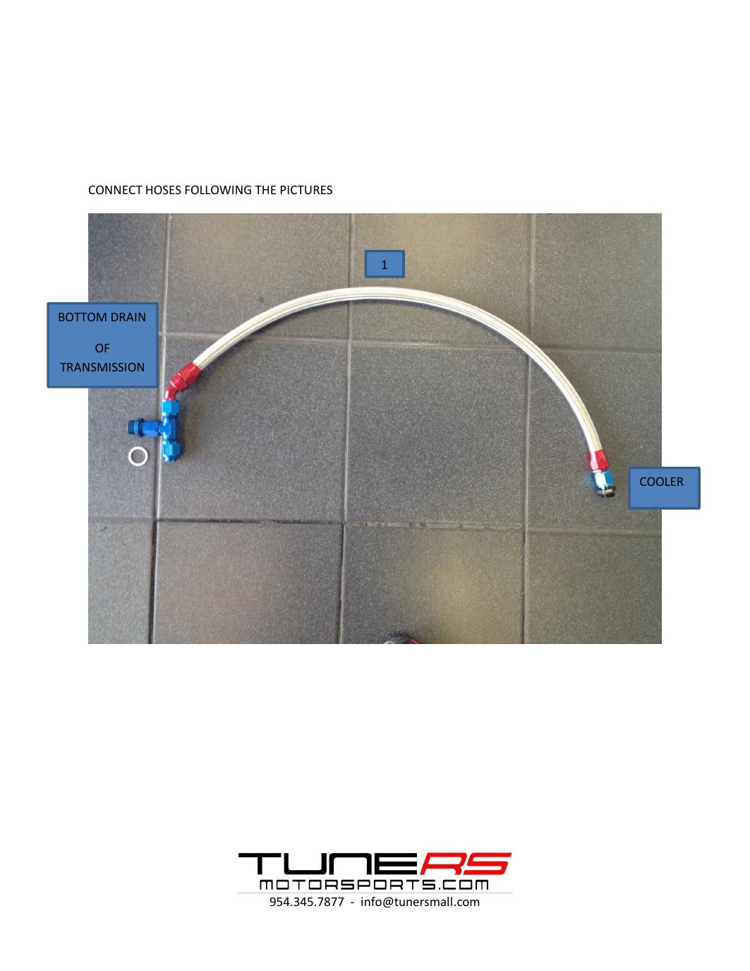
CONNECT HOSES FOLLOWING THE PICTURES

1

BOTTOM DRAIN

OF TRANSMISSION

COOLER
Original instruction sheet, page 8
Original instruction sheet — page 8. Select the image to enlarge.

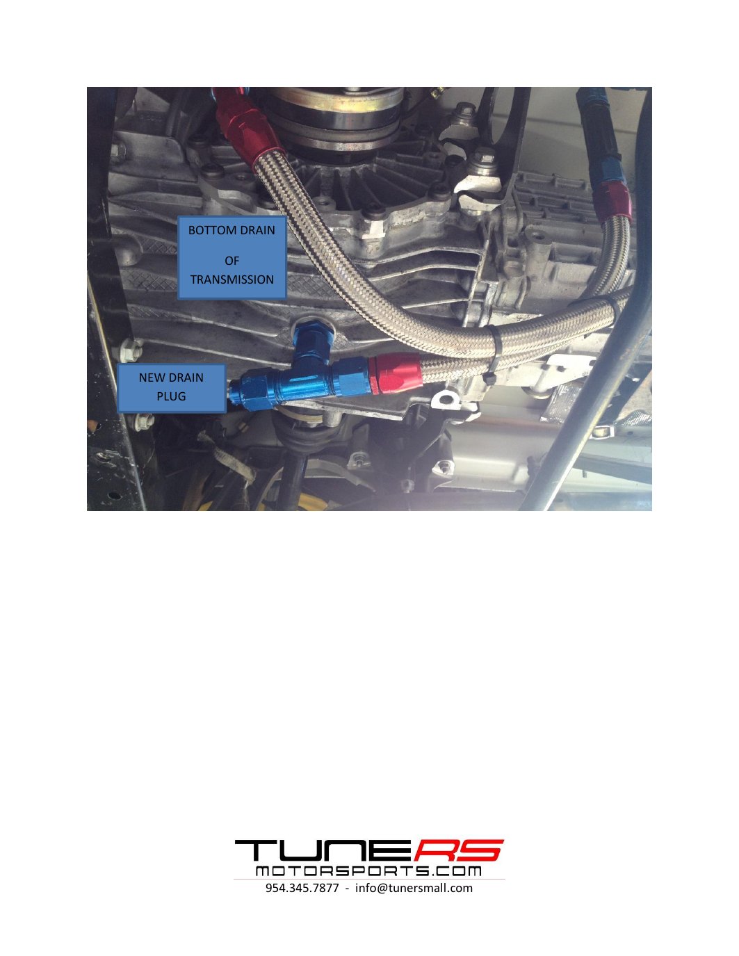
BOTTOM DRAIN

OF TRANSMISSION

NEW DRAIN PLUG
Original instruction sheet, page 9
Original instruction sheet — page 9. Select the image to enlarge.

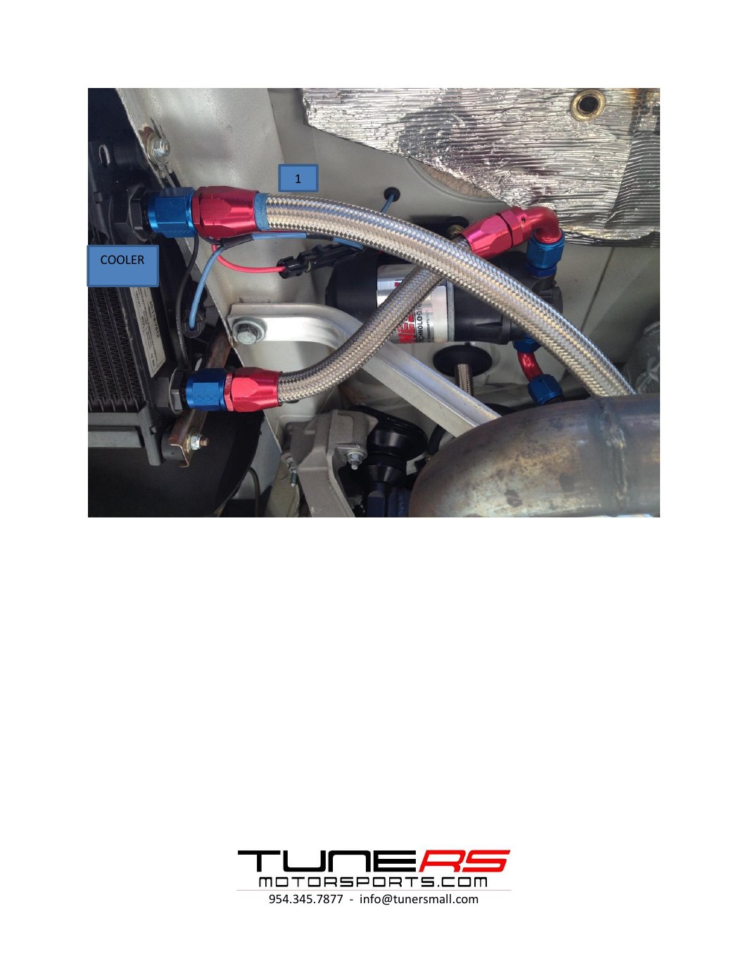
1

COOLER

Original instruction sheet, page 10
Original instruction sheet — page 10. Select the image to enlarge.
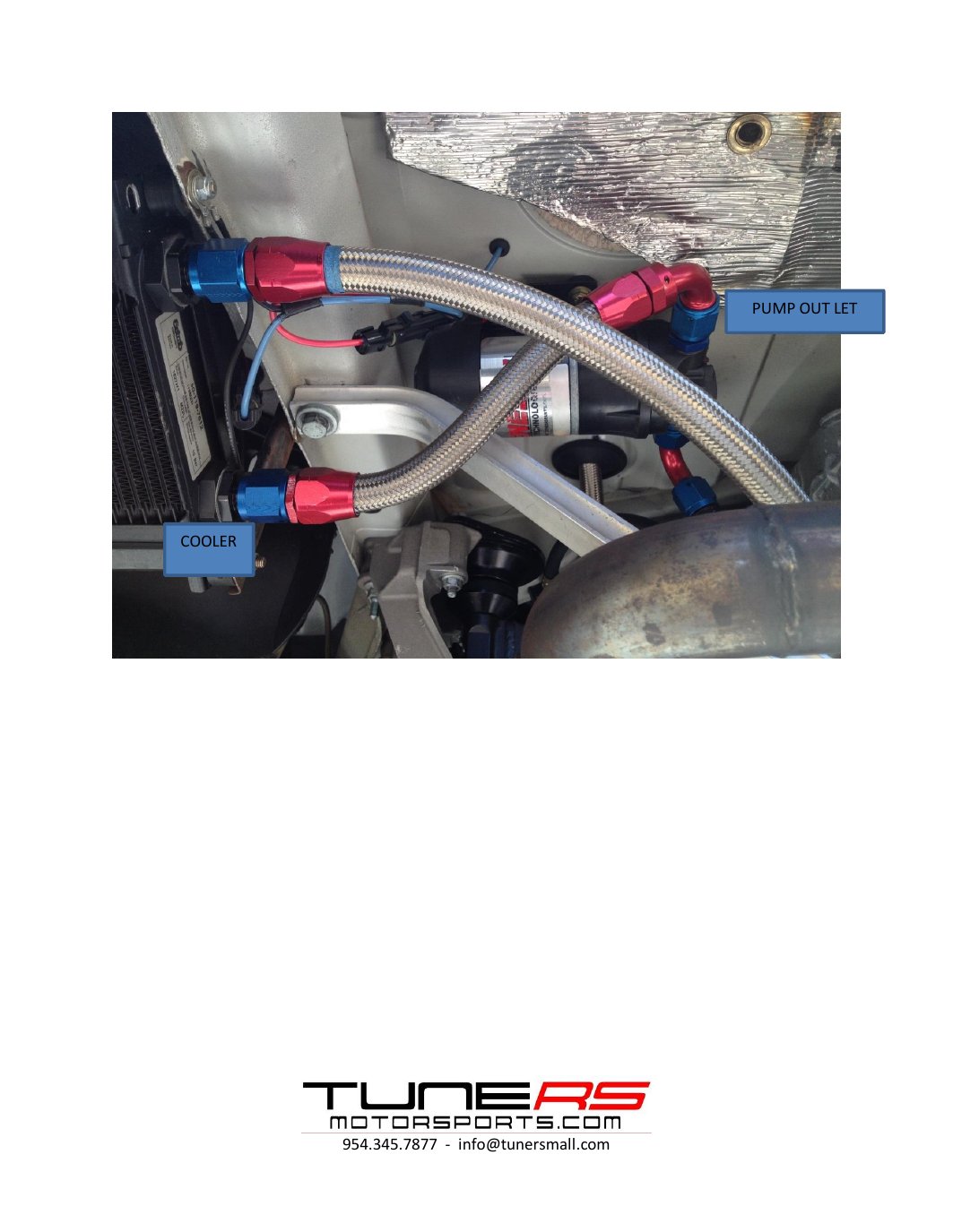
6Step 6Cooler and pump outlet connections

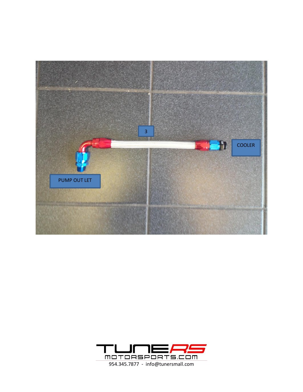
3

COOLER

PUMP OUT LET
Original instruction sheet, page 11
Original instruction sheet — page 11. Select the image to enlarge.

PUMP OUT LET

COOLER

Original instruction sheet, page 12
Original instruction sheet — page 12. Select the image to enlarge.
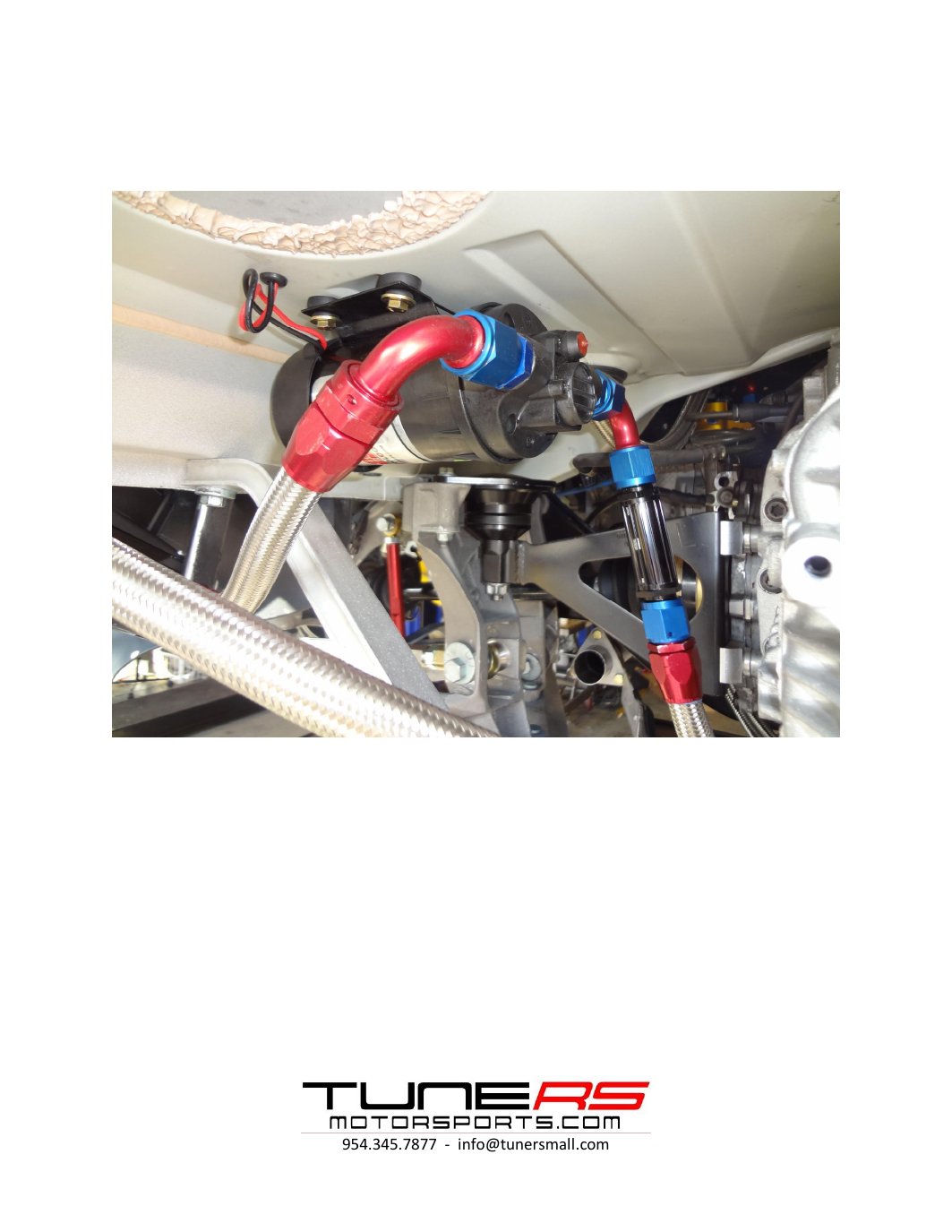
7Step 7Transmission filler and pump inlet connections

2

FILLER PLUG OF TRANSMISSION CRUSH PUMP INLET WASHER
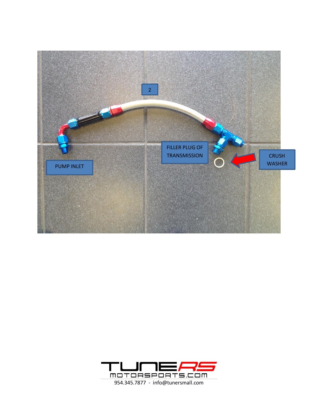
Original instruction sheet, page 13
Original instruction sheet — page 13. Select the image to enlarge.

NEW FILLER PLUG

FILLER PLUG OF TRANSMISSION
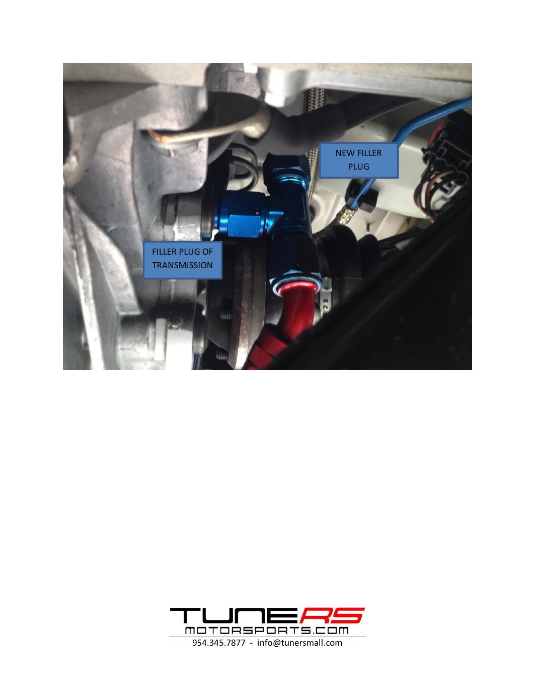
Original instruction sheet, page 14
Original instruction sheet — page 14. Select the image to enlarge.
8Step 8Pump wiring instructions

PUMP INLET

PUMP OUT LET

CONNECT ELECTRIC WIRING OF PUMP FOLLOWING INSTRUCTIONS FROM PUMP MANUFACTURE
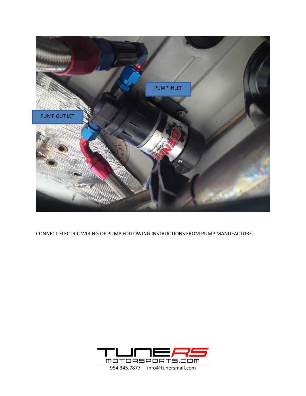
Original instruction sheet, page 15
Original instruction sheet — page 15. Select the image to enlarge.