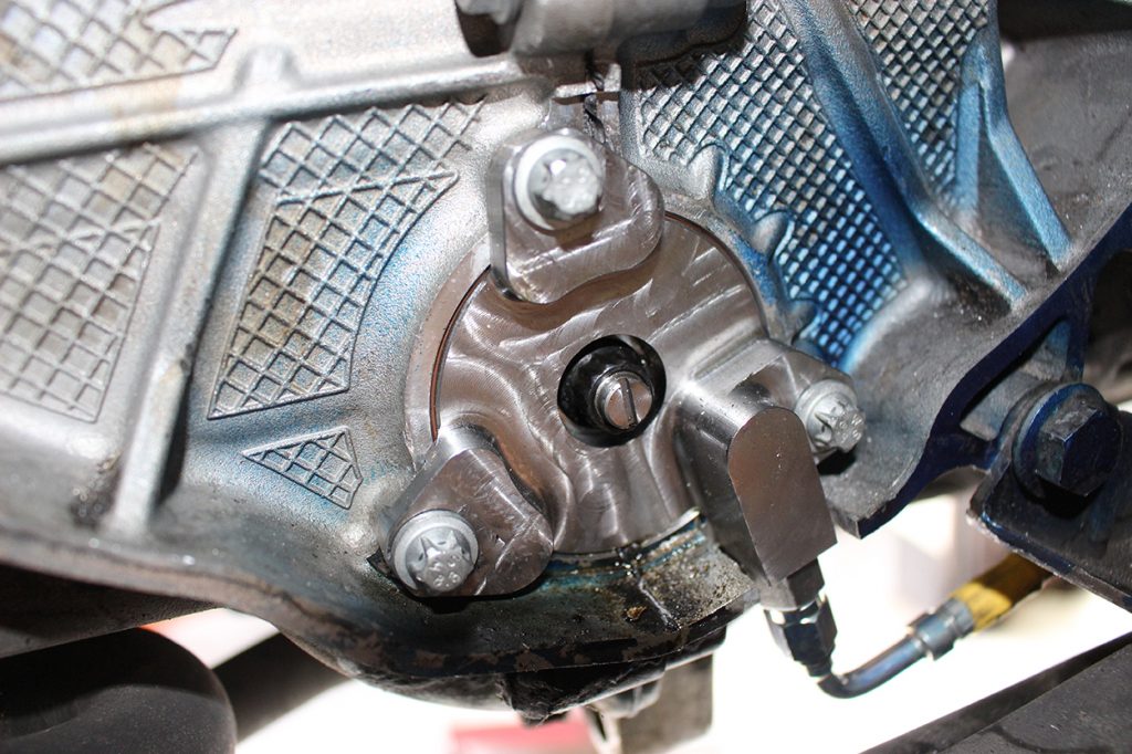
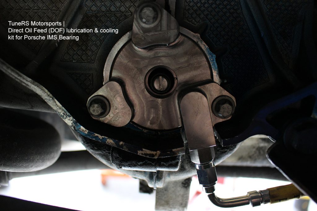
TuneRS Mall Logo
We’re expanding our online store!
We’re improving our website and adding new parts daily.
Can’t find a part or need help with an order? Contact us—we’re happy to help.
← All installation guides

TuneRS technical resources

IMS Bearing Direct Oil Feed (DOF)

Complete DOF installation, bearing identification, kit contents and version-specific instructions.

M96 / M97 · DOF1 & DOF2TRS-DOF-9705 / TRS-DOF-050856 steps
Download guide PDF
Before you begin

Here you will find the step by step installation instructions for the TuneRS Direct Oil Feed (DOF) kits version DOF1 (early 97 - 05 models) and DOF2 (late style 05 - 08 models).

TuneRS recommends professional installation for the Direct Oil Feed Kit. TuneRS takes no responsibility for improper installation of the kit. Take all precautionary safety measures. Please read through the complete instructions to familiarize yourself with the process before you attempt to do it for the first time. If you have any questions or are unfamiliar with the DOF or any IMS work, please contact us or one of your local professional installers. Failure to follow instructions properly may result in damage.

Selecting The Right DOF Upgrade Kit

Here are the DOF Upgrade Kits To Choose From:

  • The DOF Kit 1 is for M96 Porsche engines with the dual-row or single-row IMS bearing.
  • The DOF Kit 2 is for M97 Porsche engines with the larger updated IMS bearing.

After 2006, engines replaced or rebuilt on 1997 - 2005 Porsche models by Porsche directly may have the larger updated IMS bearing which will require the TRS-DOF-0508 (DOF2) kit.

**IMPORTANT NOTES FOR TRS-DOF-9705 KIT (DOF1) INSTALLATION**
Previous versions of our DOF1 kits were supplied with two spacer rings. Newer versions (June 2015+) have one spacer ring for Single Row bearing installations only. Do not attempt to install the spacer ring for a Dual Row bearing or improper fitment & damage will occur.

**IMPORTANT UPDATE BEGINNING JANUARY 2021 ON DOF1 INSTALLATION**

The Direct Oil Feed kit now has an updated shaft bolt; it is larger in diameter. We have done this due to customers starting to run over 8000+rpm and high horsepower on their M96 engines for reliability purposes. All kits starting January 2021 will have this.

If you are an authorized installation shop and have an IMS bearing tool kit, you will need to modify the existing aluminum cylinder insertion tool to allow the larger shaft bolt to fit. Simply drill your existing tool component to the larger diameter of 13mm. If you are a DIY customer and purchased or rented the tool kit from us, the specific tool has already been modified for this.

Determining The Correct Bearing

Before you order your DOF kit, make sure to determine which type of IMS bearing is equipped on your Porsche. There is no 100% way to know what bearing type you have and the only accurate way to know is to already have access to your IMS flange (transmission removed). If you already know what bearing your Porsche model is equipped with and need to order a kit please give us a call.

  • 1997 - 2000 Porsche Boxster and Carrera models will have dual row.
  • 2001 - 2004 Porsche Boxster and Carrera models will have single row.
  • Some early production 2005 models have also had the single row style equipped.
  • 2005 - 2008 Porsche Boxster, Cayman and Carrera models are equipped with the larger style bearing that is not extractable

Identifying your bearing by the IMS flange:

  • The dual row bearing will have a shallow flange
  • The single row bearing will have a deep flange
  • The later style larger bearing will have a shallow flange with a larger nut.

IMS Engine Flange Comparisons

Before you begin — photo 1

It is very important that before proceeding with any IMSB replacement that you first inspect your engine. Remove the engine oil pan cover to inspect for any debris. At this time it is also a good idea to clean the oil pickup tube. If you have found any metal shavings or fragments, do not continue further as internal engine damage is already present. We also recommend to remove the engine oil filter and open it to inspect for any metal debris. Again, if any debris is found do not move forward.

INSTALLATION INSTRUCTIONS:

These instructions begin after the shop has removed the transmission from the vehicle according to Porsche’s recommendations. Perform this at your own risk.

Tools & equipment
  • Auto Lift
  • Air/electric grinder with bit (or hand saw and assortment of files)
  • Flat-blade screwdrivers
  • Flat-bladed pry bars
  • Selection of sockets including 32 mm for chain tensioner
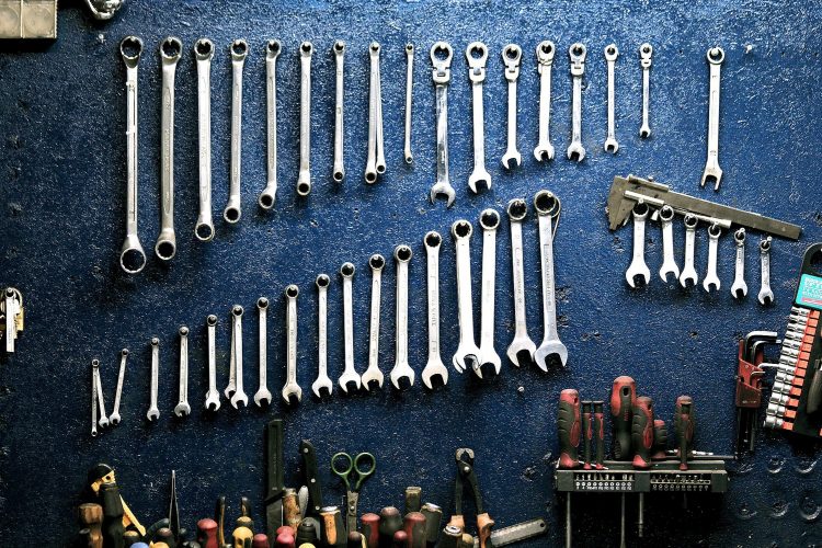
  • Selection of wrenches
  • Hex allen wrench for oil plug
  • Spring-clip (c-clip) removal/insertion pliers
  • IMS bearing extraction tool (if replacing the existing bearing)
  • IMS bearing insertion tool (if replacing the existing bearing)
  • Soft-faced mallet/hammer
  • Grease
  • Work gloves
  • Rags/paper towels
  • Engine oil catch can

Tools & equipment — photo 1

Kit contents

Parts included in each kit:

  • Patented DOF flange housing with 3 ribbed seal
  • M14x1.5 (19 mm hex) oil line adapter with crush washer
  • Oil line straight fitting with o-ring
  • Tube of thread lock
  • 3 new M6x20 micro-encapsulated flange housing bolts
  • High-pressure flexible oil line (3,000 psi rated DOT)
  • Camshaft housing plugs (qty 2)
  • IMS bearing support shaft with nut and o-ring seal (for early single/dual row bearings)
  • Retaining clip for IMS bearing (early single/dual row)
  • Spacer ring for early single row bearings

Cars with the double-row bearing use the circlip provided & have no spacer ring required.
Cars with the single-row bearing use the spacer ring & circlip provided with the bearing.

Installation steps

1Step 1Remove the clutch assembly or torque converter
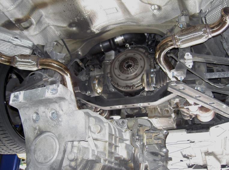
Remove the clutch assembly (or torque converter).

Remove the clutch assembly or torque converter — photo 1
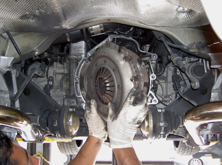
Remove the clutch assembly or torque converter — photo 2

2Step 2Remove the dual-mass flywheel
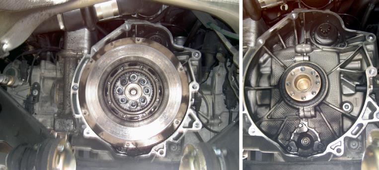
Remove the dual-mass flywheel.

Inspect the rear main seal (RMS) and determine if it will be replaced due to leaks. If replacement is needed, do so after the DOF installation. We highly recommend replacing the RMS at the same time as the labor to access is already being performed. We recommend using the original Porsche rear main seal.
Remove the dual-mass flywheel — photo 1

3Step 3Mark the bell-housing cutout
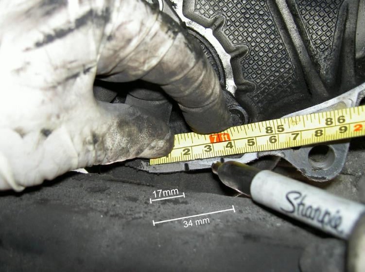
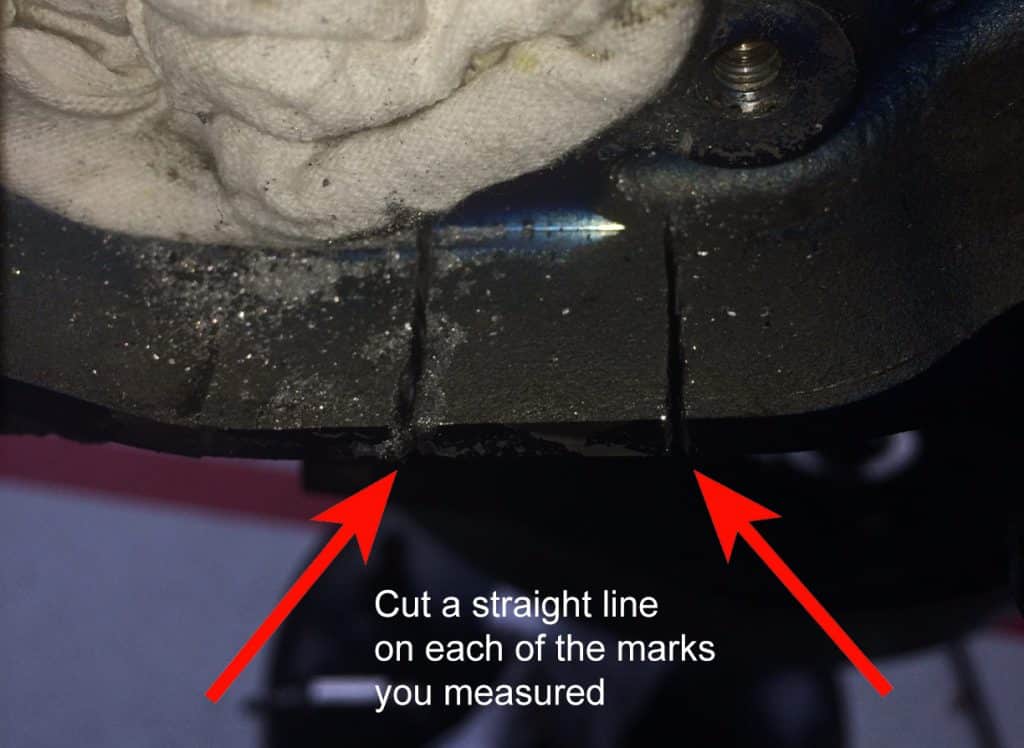
Using a straight ruler or caliper and marker, on the bottom of the exposed bell housing edge on the engine, from the center, just under the IMS bearing, measure and place a mark at 17 mm and a second mark at 34 mm to the right of the center (as you’re looking at it).

Mark the bell-housing cutout — photo 1

Mark the bell-housing cutout — photo 2

4Step 4Clean the surrounding area
Clean the surrounding area of soot and debris.

Clean the surrounding area — photo 1

5Step 5Move the safety cable or sway bar
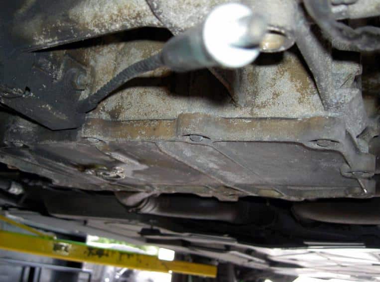
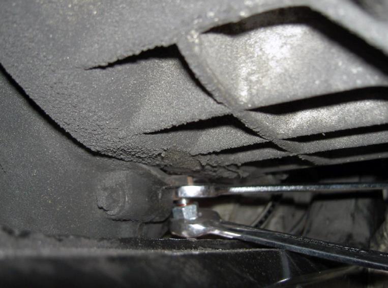
To allow you more working room, on the Boxsters remove the side of the engine’s lower safety cable from the engine support yolk immediately under where you will be grinding into the bell housing. On the Carreras, loosen and move out of the way the rear sway bar.

Move the safety cable or sway bar — photo 1

6Step 6Cut the bell-housing notch
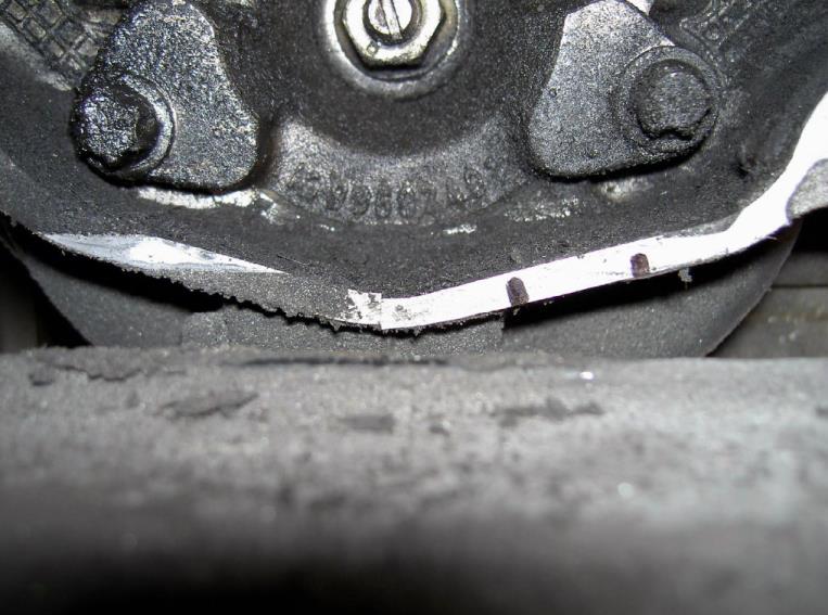
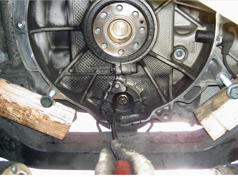
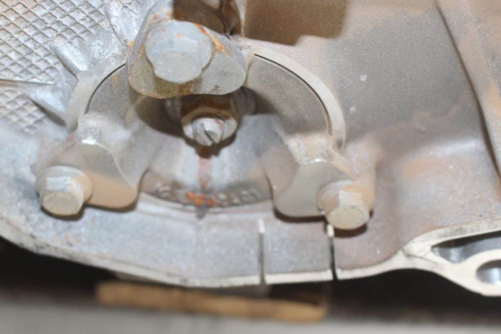
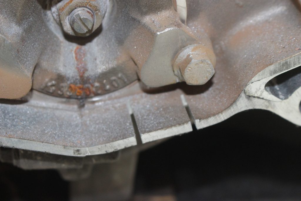
Using an electric or air grinder and correct bit for soft metal and/or a hand saw, cut at the measured marks on the bell housing edge. Cut all the way through the bell housing nerve up to but not into the engine case. It is important that you do this step BEFORE removing the flange - this will prevent any possibility of metal shavings getting into the engine. This process can be messy. Make sure to wear the proper eye protection as well.

Cut the bell-housing notch — photo 1

Cut the bell-housing notch — photo 2

Cut the bell-housing notch — photo 3

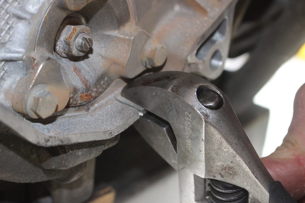
Once you have made your two initial cuts (shown above), use an adjustable wrench to grab the newly created "tab" to break the piece off.
Cut the bell-housing notch — photo 4

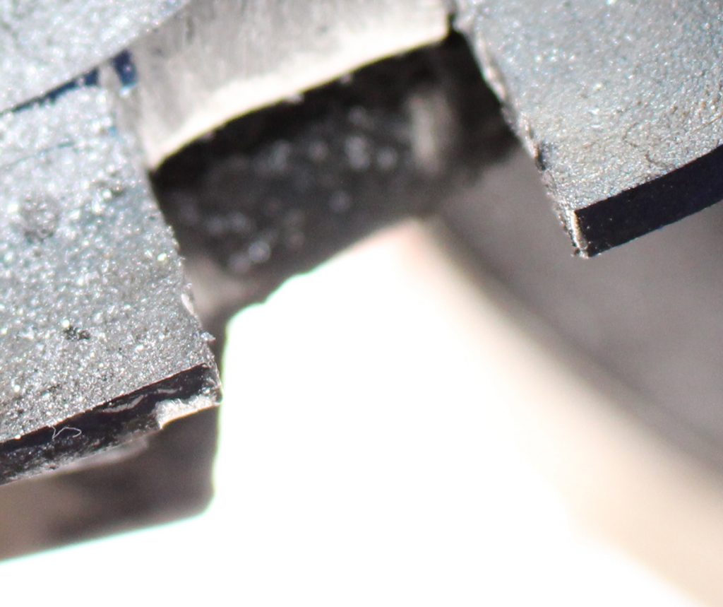
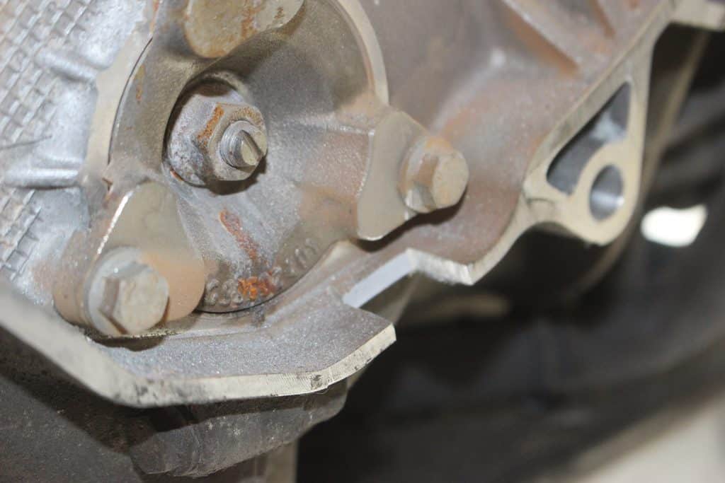
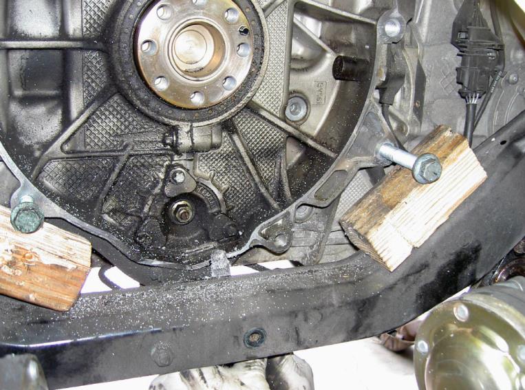
This is the result of the notch that has been created. Once you are here, you will need to finish the notch by using a file or dremel to clean the edges.
Cut the bell-housing notch — photo 5

Cut the bell-housing notch — photo 6

7Step 7Remove debris and finish the notch
Clean all of the metal debris.

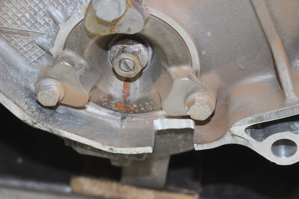
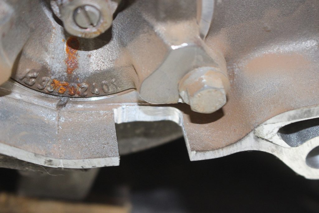
This is how the final notch should look after you have done your measuring and cutting. Use a file to clean the edges.
Remove debris and finish the notch — photo 1

Remove debris and finish the notch — photo 2

Remove debris and finish the notch — photo 3

8Step 8Set TDC and lock the camshaft
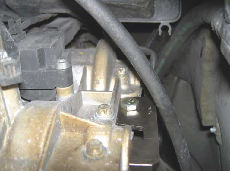
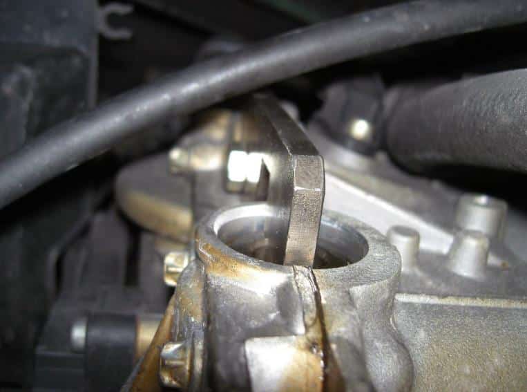
Put the engine in top dead center (TDC). Lock camshaft on cylinder bank 1-3. On the Boxsters/Caymans, remove the right camshaft plug and lock cam in place with the correct locking key. On the Carrera it’s the left camshaft.

Set TDC and lock the camshaft — photo 1

Set TDC and lock the camshaft — photo 2

9Step 9Lock the crankshaft
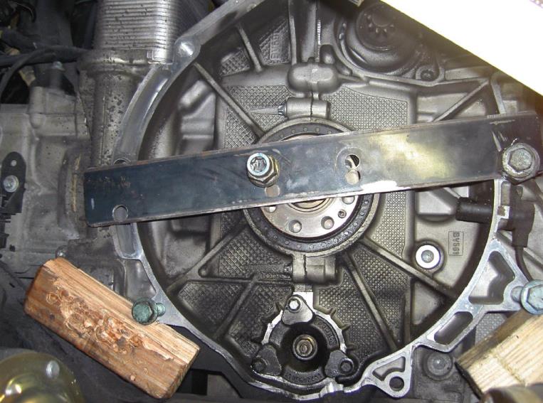
Also, lock the engine’s crankshaft to avoid any movement during installation.

Lock the crankshaft — photo 1

10Step 10Drain the engine oil
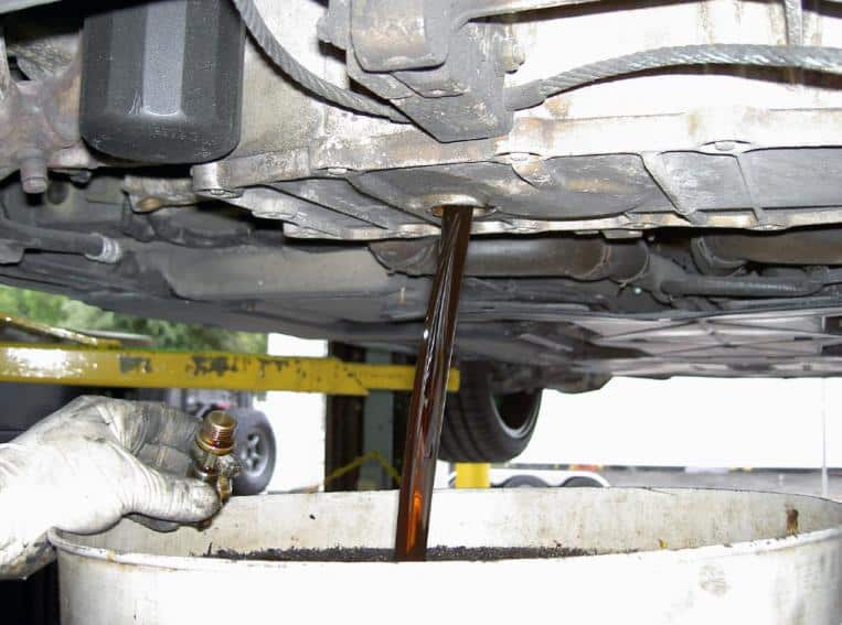
Drain the engine oil.

Drain the engine oil — photo 1

Chain tensioner removal

11Step 11Remove the chain tensioners
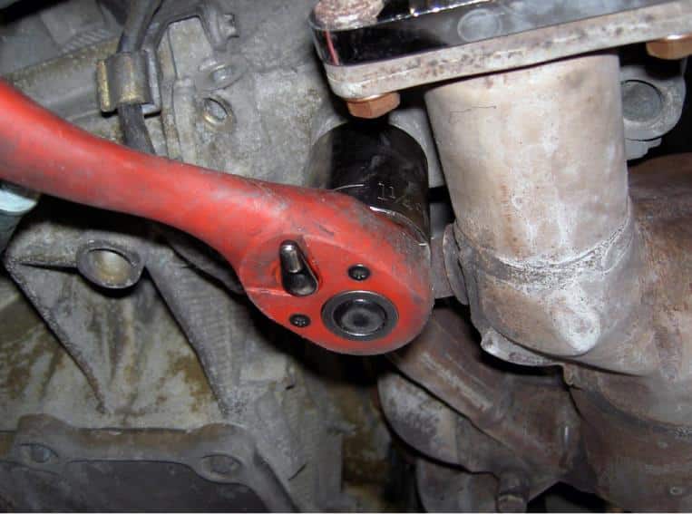
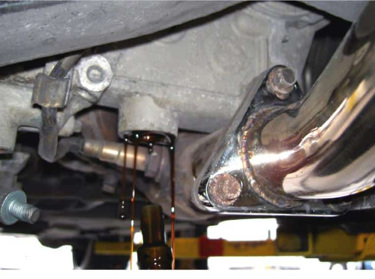
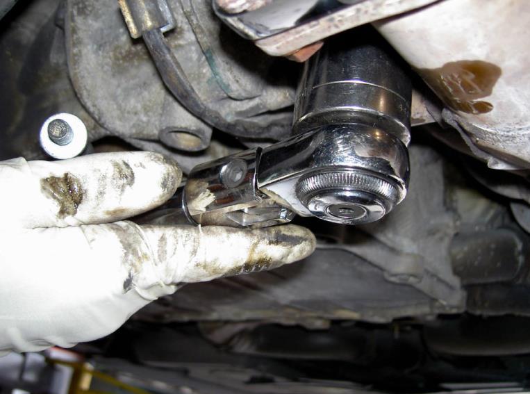
Using a 32 mm socket, remove the bank 1-3 chain tensioner (on the Boxster the right / on the Carrera the left). Be prepared to catch oil. You will also need to remove the primary chain tensioner. Be prepared to catch oil. After chain tensioner removal, the crankshaft must NOT be turned under any circumstances otherwise the timing chain may jump over.

Remove the chain tensioners — photo 1

Remove the chain tensioners — photo 2

Now begins the Flange & Bearing removal steps

12Step 12Remove the bearing support nut
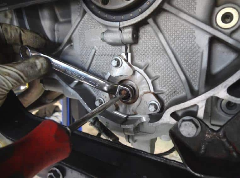
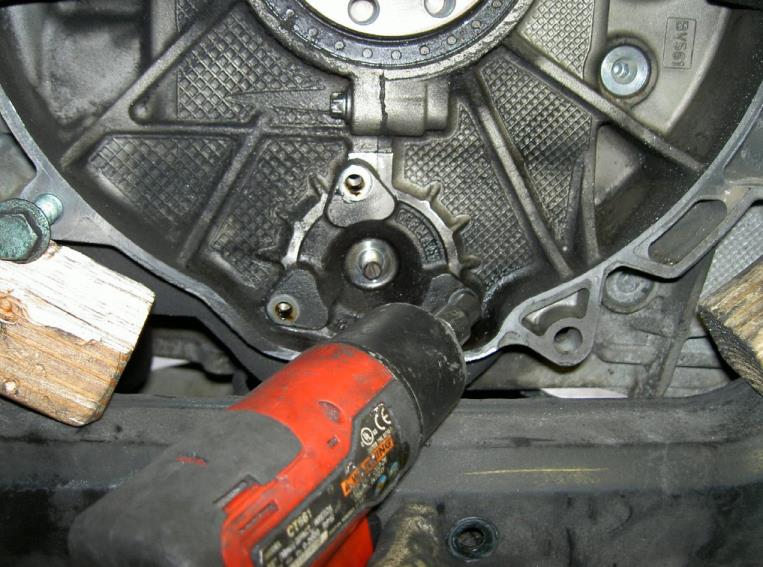
Holding the end of the bearing support shaft with a flat screwdriver, loosen and remove the center nut.

Remove the bearing support nut — photo 1

13Step 13Remove the flange bolts
Remove the three flange support bolts.

Remove the flange bolts — photo 1

14Step 14Remove the existing flange
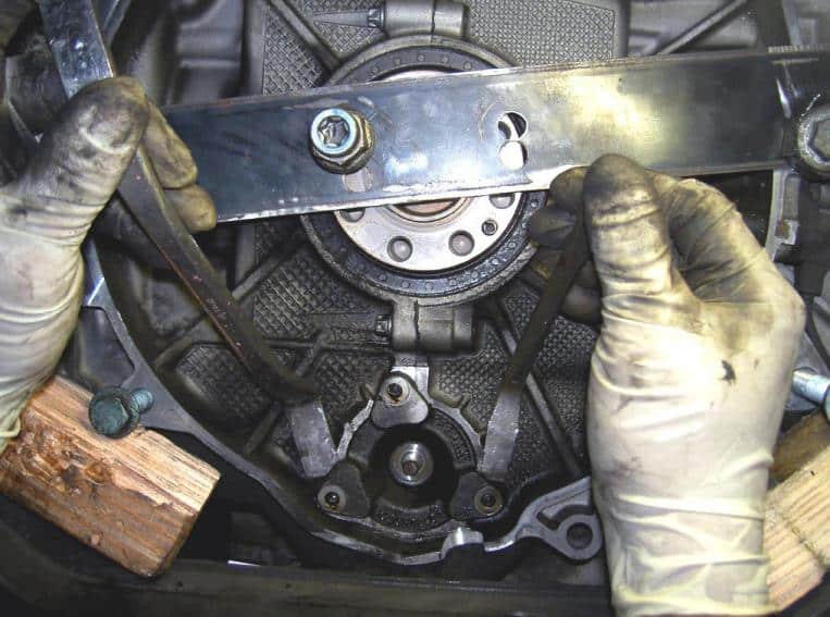
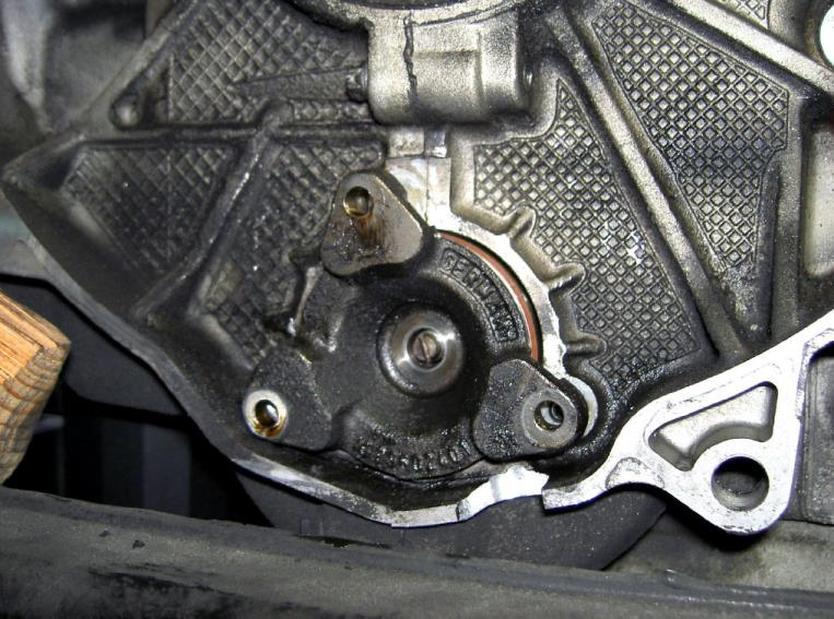
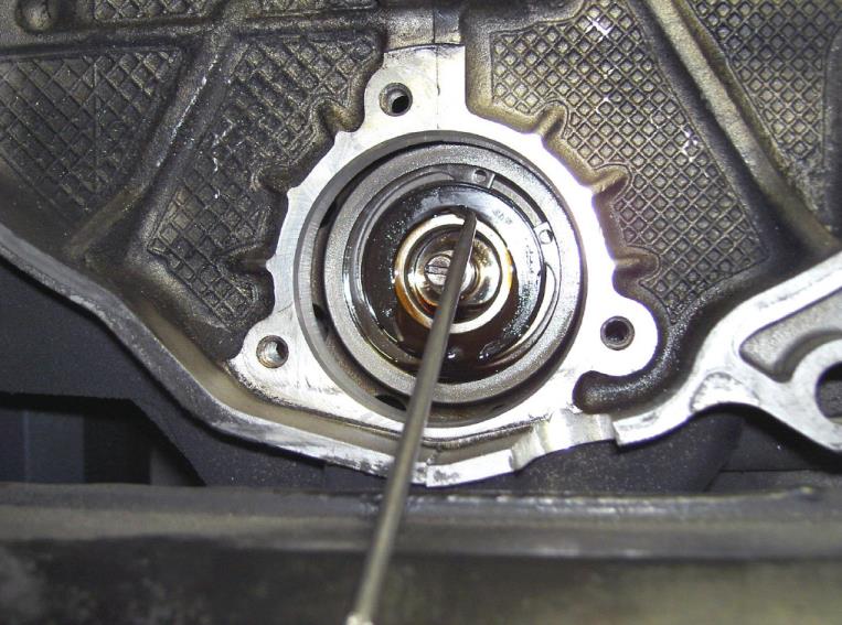
Using a couple of flat-bladed pry bars or strong screwdrivers slowly and carefully pry out the existing bearing flange. Be prepared to catch oil.

Remove the existing flange — photo 1

Remove the existing flange — photo 2

Remove the existing flange — photo 3

NOTE:
On the later style larger bearings (non extraction), simply remove the outer seal of the IMS bearing. Skip the steps below showing “IMS bearing removal/install” as this does not apply
to you.

15Step 15Inspect the bearing shaft
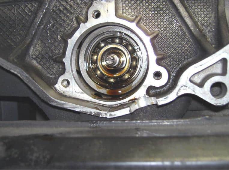
Test to see if there is any movement (slop) in the bearing’s shaft. Lateral movement (slop) means that the bearing has started to wear down.

NOTE: If installing the TRS-DOF-9705 (DOF1) kits with either a dual row or single row bearing, you MUST use the bearing that was purchased with the DOF kit for your vehicle. Other aftermarket bearings such as ceramic or roller will not fit with the custom DOF flange and if another brand & style of bearing is used with the DOF other than what was supplied damage will occur due to improper fitment and we take no responsibility for incorrect installation.

16Step 16Remove the outer seal on the larger bearing

Larger, non-extractable IMS bearing — read the DOF2 / replacement-engine notes.
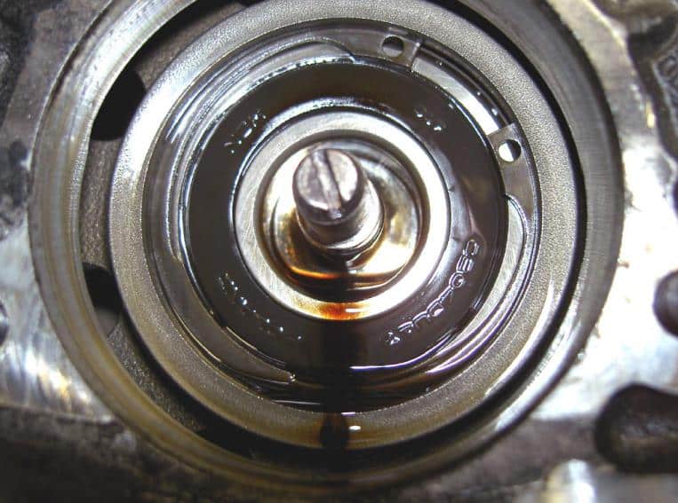
On the later style Boxster / Cayman / Carrera (MY 2005 - 2008) or vehicles equipped with replacement Porsche engines after 2006 that have the larger IMS bearing that cannot be extracted, simply remove the outer seal of the exposed IMS bearing. Failure to remove the outer seal will warrant the DOF kit useless as the filtered & cooled oil will not be able to contact the ball bearing.

Remove the outer seal on the larger bearing — photo 1

Remove the outer seal on the larger bearing — photo 2

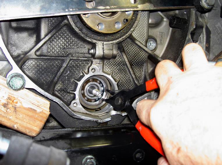
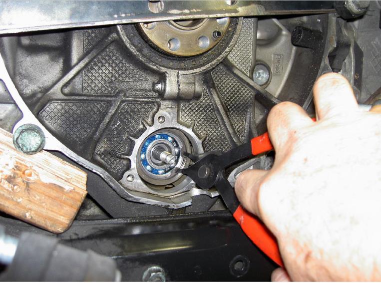
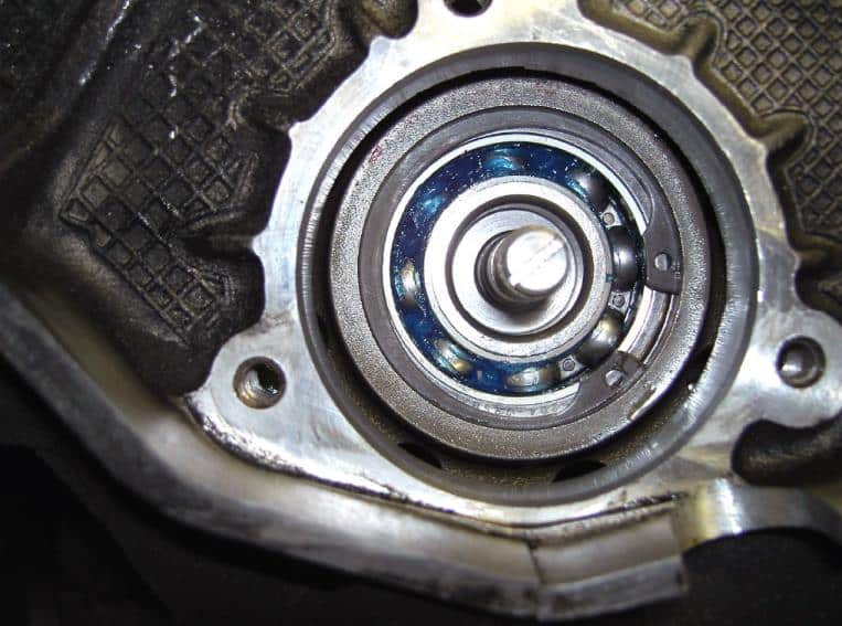
17Step 17Remove the retaining clip
With the IMS bearing exposed, remove the retaining clip. This step does not apply to 997/987 with larger IMS bearing.

Remove the retaining clip — photo 1

18Step 18Attach the bearing removal tool bolt
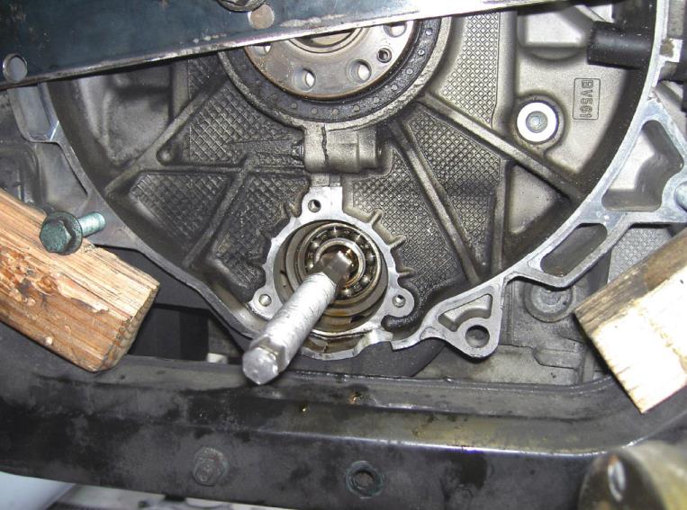
Screw the center bolt from the bearing removal tool onto the bearing’s support shaft and tighten by hand.

Attach the bearing removal tool bolt — photo 1

19Step 19Position the bearing removal tool
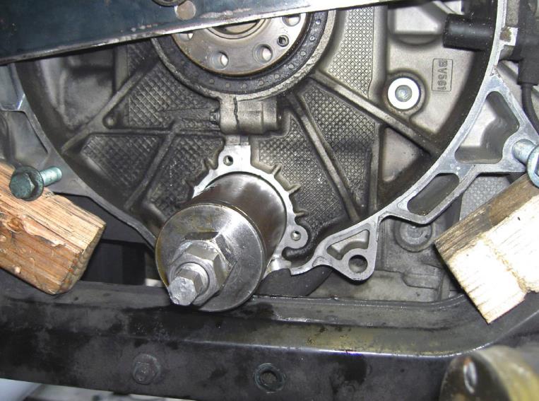
Place the bearing removal tool onto the center bolt and tighten the main nut by hand so that the tool is completely against the engine case.

Position the bearing removal tool — photo 1

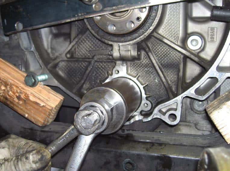
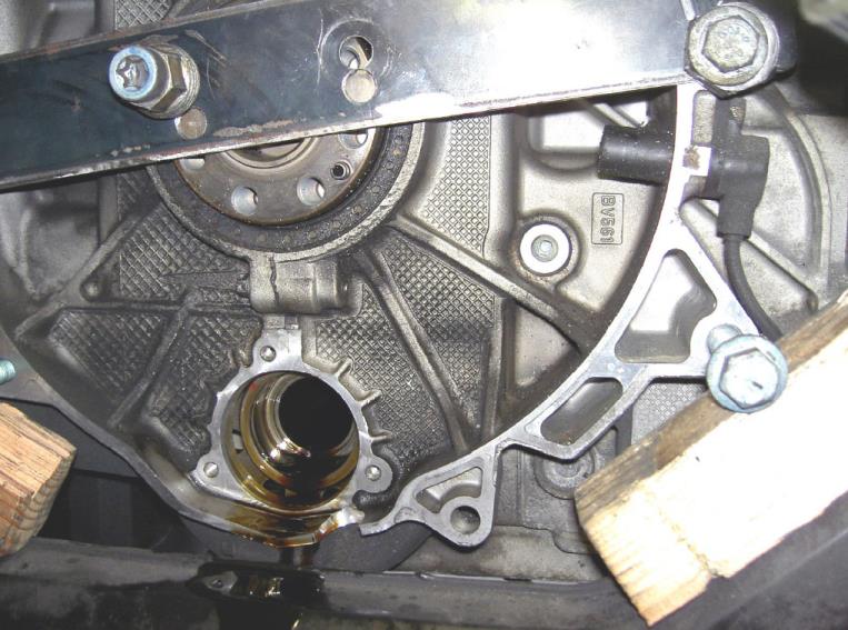
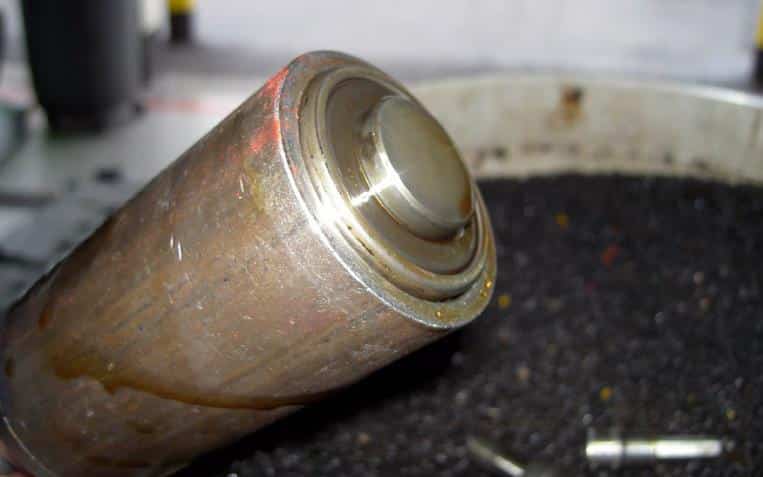
20Step 20Extract the bearing
With a wrench, hold the center bolt so it doesn’t rotate and start tightening the main nut slowly. At some point you may hear a loud pop which is normal. Keep tightening the main nut until the bearing is completely removed. The bearing will come out inside the removal tool. Be prepared to catch oil.

Extract the bearing — photo 1

Extract the bearing — photo 2

Extract the bearing — photo 3

21Step 21Clean the intermediate shaft and prepare the new bearing
Clean out the open end of the IMS. Leave a thin film of oil or grease so that the new bearing slides in easier.

Steps to prepare and install the new IMS bearing

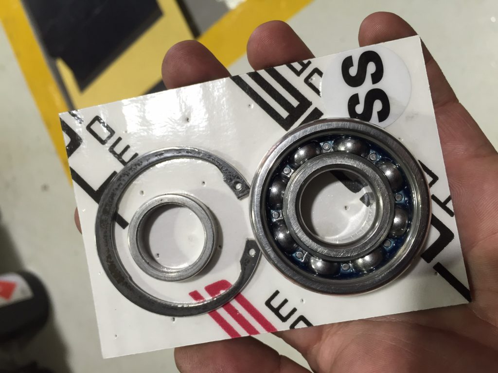
Here is how your new SKF steel IMS bearing should have arrived, packaged with the correct spacer ring and clip. These bearings are made to work with our DOF flange.
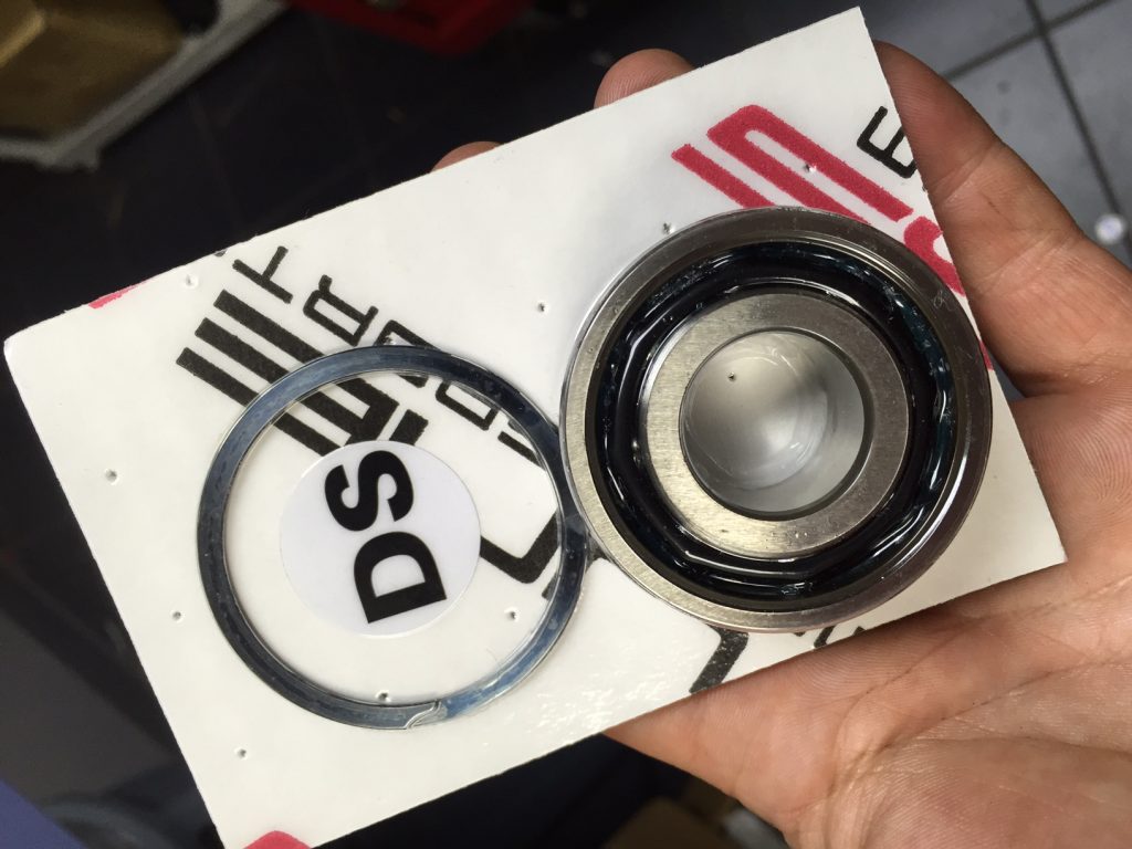
Clean the intermediate shaft and prepare the new bearing — photo 1

(DS = Dual steel)

Clean the intermediate shaft and prepare the new bearing — photo 2

(SS = Single steel)

UPDATE AS OF JANUARY 2021

The Direct Oil Feed kit now has an updated shaft bolt; it is larger in diameter. We have done this due to customers starting to run over 8000+rpm and high horsepower on their M96 engines for reliability purposes. All kits starting January 2021 will have this.

THE UPDATED TORQUE ON THE CENTER NUT FOR THE DOF1 SHAFT BOLT IS 18ft/lbs

22Step 22Install the new bearing support shaft
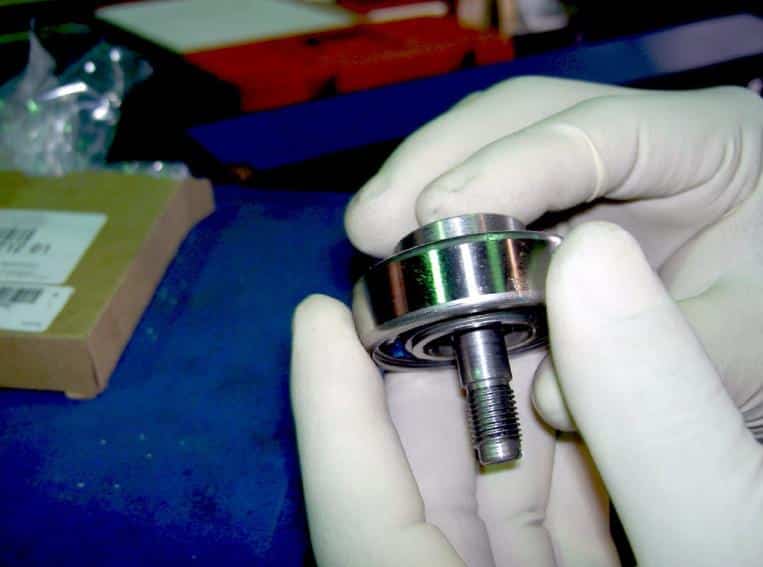
Place the new bearing support shaft onto the new bearing. Make sure that the open side of the bearing faces towards the shaft’s threaded end.

Install the new bearing support shaft — photo 1

23Step 23Seat the shaft in the bearing
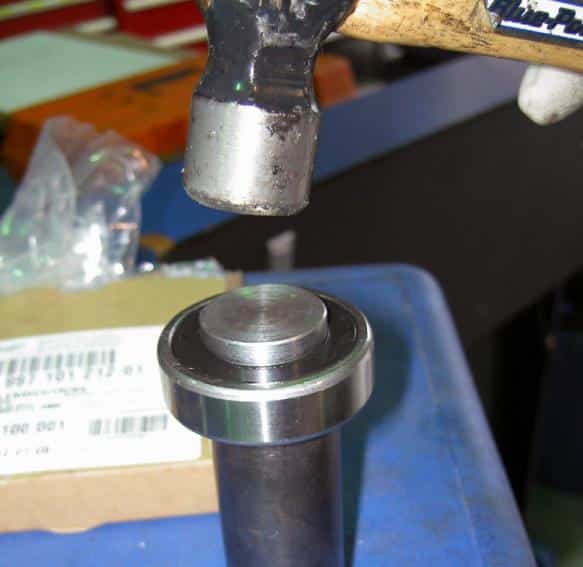
Place the bearing with the shaft in place over a socket of the correct size which can support the inner race of the bearing and lightly tap the end of the shaft completely onto the bearing’s inner race.

Seat the shaft in the bearing — photo 1

24Step 24Load the bearing insertion tool
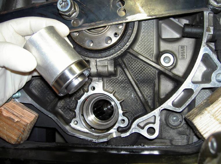
Place the assembly into the bearing insertion tool.

Load the bearing insertion tool — photo 1

25Step 25Center the insertion tool
Carefully center over the bearing’s seat.

Center the insertion tool — photo 1

26Step 26Seat the bearing
Tap the end of the insertion tool until the bearing is seated completely. You will hear a “solid” change in sound when the bearing has reached the engine block.

Seat the bearing — photo 1

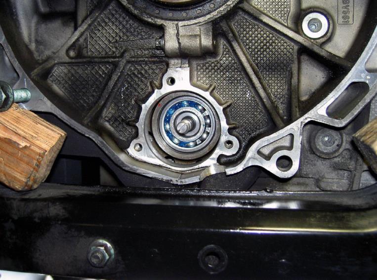
27Step 27Remove the insertion tool
Pull the insertion tool out. The correctly installed bearing should look like this:

Remove the insertion tool — photo 1

28Step 28Install the retaining clip
Using the proper C-clip pliers insert the new retaining clip (supplied).

Install the retaining clip — photo 1

Install the retaining clip — photo 2

Steps to prepare and install the DOF flange

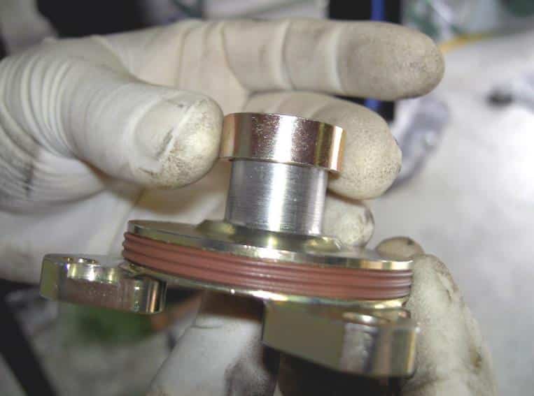
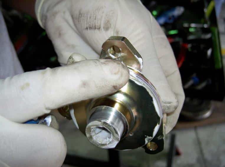
29Step 29Fit the correct spacer ring
Insert the spacer ring (supplied) onto the DOF (only if single row bearing is being installed. Dual row does not have spacer). **Most of the early DOF kits prior to June 2015 had a spacer for both dual and single row. These kits are no longer in supply and the newer version is now supplied with only 1 spacer ring for the single row IMS bearing. If you have any questions contact us before proceeding.

Fit the correct spacer ring — photo 1

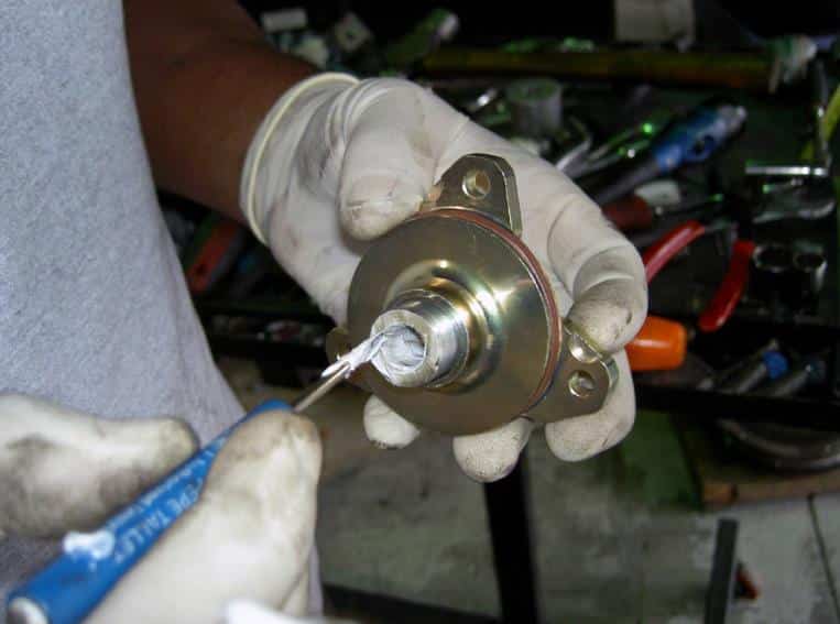
30Step 30Lubricate the DOF flange
Smear a bit of high-quality white lithium grease on the inside of the DOF shaft and on the outside red sealing ring.

Lubricate the DOF flange — photo 1

Lubricate the DOF flange — photo 2

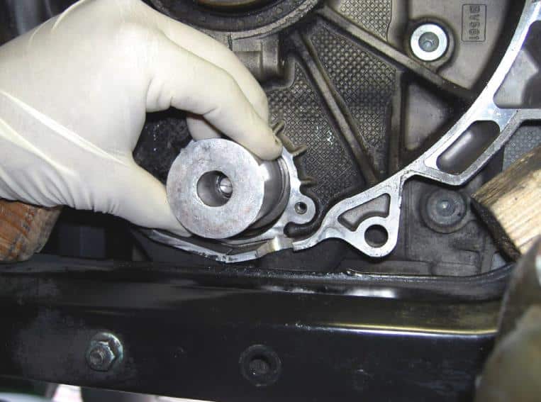
31Step 31Position the new DOF flange
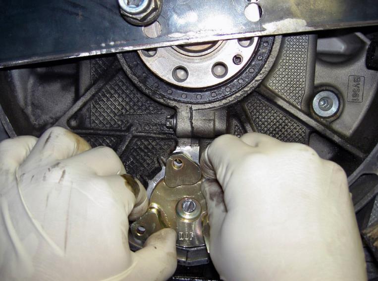
Place the new DOF flange with spacer ring in place onto the bearing support shaft.

Position the new DOF flange — photo 1

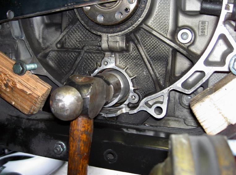
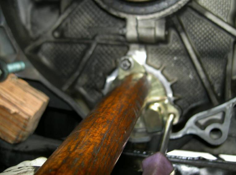
32Step 32Seat the DOF flange
Thread one of the old, removed bolts in place on the top most hole of the flange. Insert a phillips screwdriver or punch-pin into one of the two remaining holes and carefully use as a lever to gently guide the flange into position. Once in position, using the butt end of a hammer’s wooden handle or a soft-faced mallet, tap the flange into place. Remove the old bolt.

Seat the DOF flange — photo 1

33Step 33Check oil-line fitting clearance
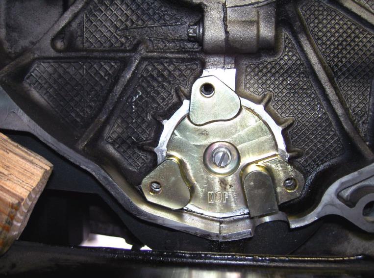
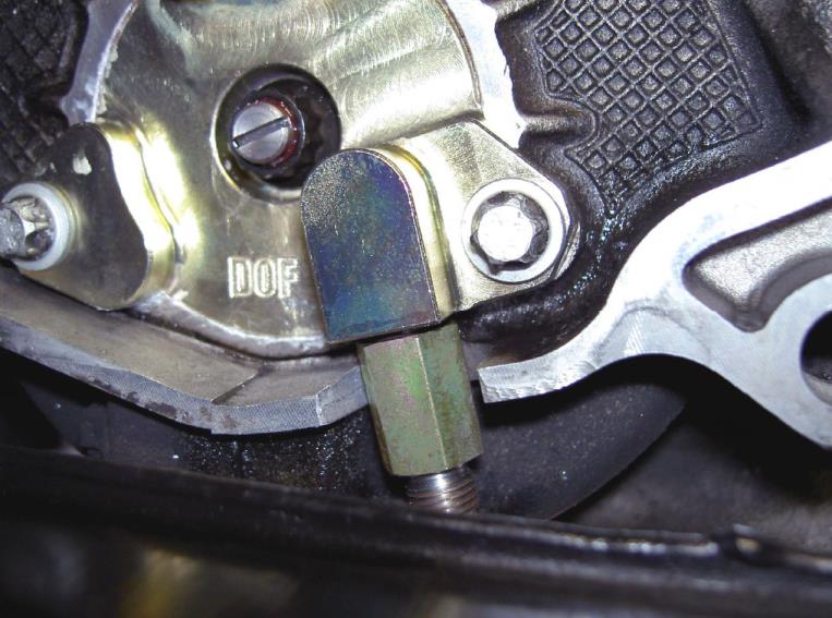
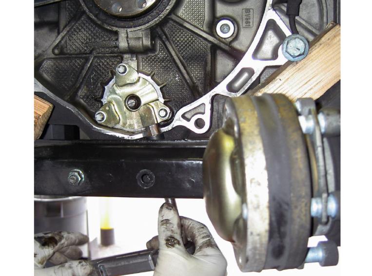
Check the clearance for the DOF/Oil line screw-in adapter on the bell housing cut-out that you made before. Adjust the clearance if necessary with a file.

Check oil-line fitting clearance — photo 1

34Step 34Install the new flange bolts
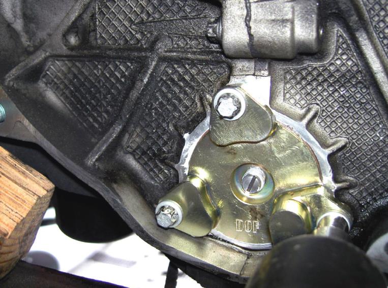
Insert the three new, micro-encapsulated flange bolts (supplied) and thread by hand.

Install the new flange bolts — photo 1

35Step 35Tighten the flange bolts evenly
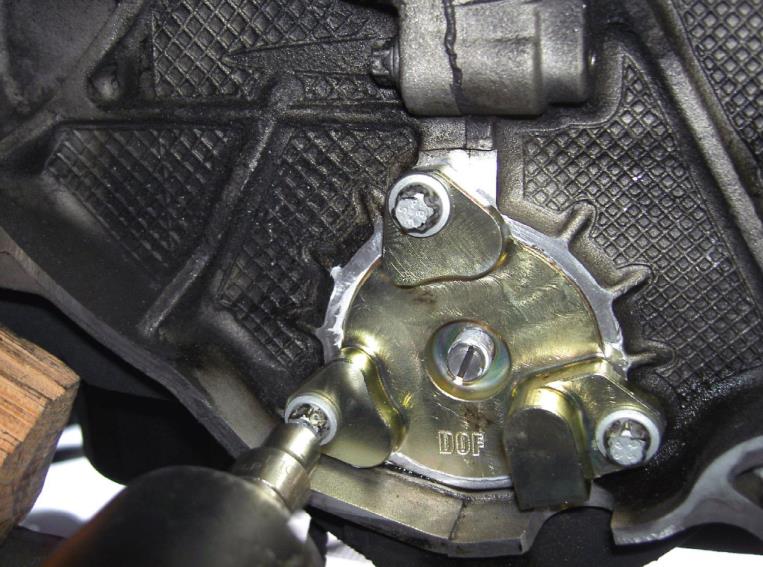
Tighten each bolt only a few turns at a time and move to the next one. This assures that the flange gets inserted correctly.

Tighten the flange bolts evenly — photo 1

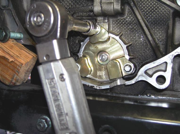
36Step 36Torque the flange bolts
Once all three bolts are completely screwed in and the flange has been seated, tighten to a torque of 10 Nm (7.5 lb-ft or 88.5 lb-in).

Torque the flange bolts — photo 1

37Step 37Install and torque the center nut
Put a bit of thread locker (supplied) onto the threads of the new bearing support flange nut (supplied) and thread in place by hand.

DOF1 center nut torque – 15 Nm (11 lb-ft or 132 lb-in)

THE UPDATED TORQUE ON THE CENTER NUT FOR THE DOF1 SHAFT BOLT IS 18 lb-ft. IF YOU HAVE THE LATEST UPDATED DOF1 KIT PLEASE MAKE SURE TO FOLLOW THIS NEW TORQUE. 

DOF2 center nut torque – 19 Nm (14 lb-ft or 168 lb-in)
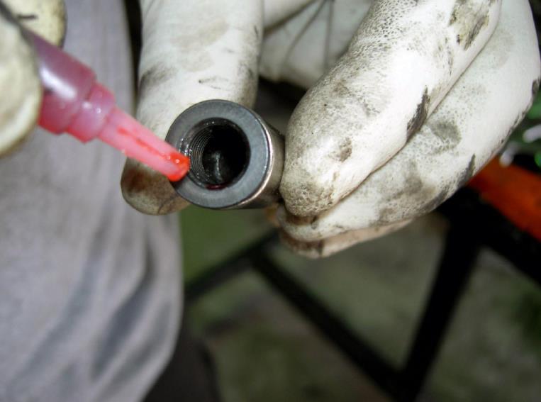
Install and torque the center nut — photo 1

Install and torque the center nut — photo 2

38Step 38Prepare the straight hose adapter
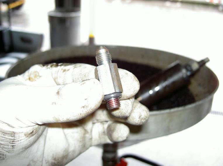
Put a bit of thread locker (supplied) onto the threads of the straight hose adapter on the O-ring side.

Prepare the straight hose adapter — photo 1

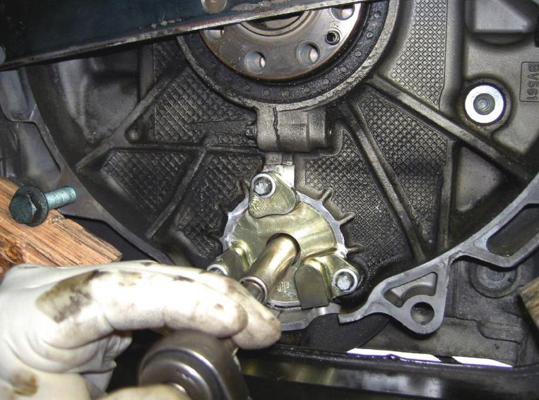
39Step 39Install the straight hose adapter
Thread into place onto the DOF flange. Note that the o-ring end of the hose adapter screws into the DOF.

Tighten to a torque of 10 Nm.

Install the straight hose adapter — photo 1

Install the straight hose adapter — photo 2

40Step 40Clean the chain tensioner
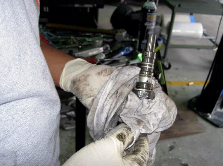
Clean the previously removed chain tensioner.

Clean the chain tensioner — photo 1

41Step 41Install and torque the chain tensioner
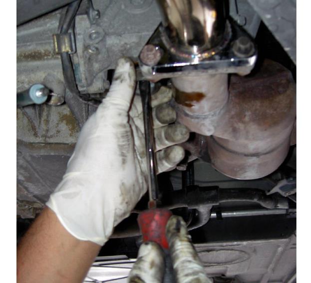
Insert and tighten the chain tensioner.

Torque to 80 Nm (59 lb-ft).

Install and torque the chain tensioner — photo 1

Install and torque the chain tensioner — photo 2

42Step 42Remove the cam lock and install the seal
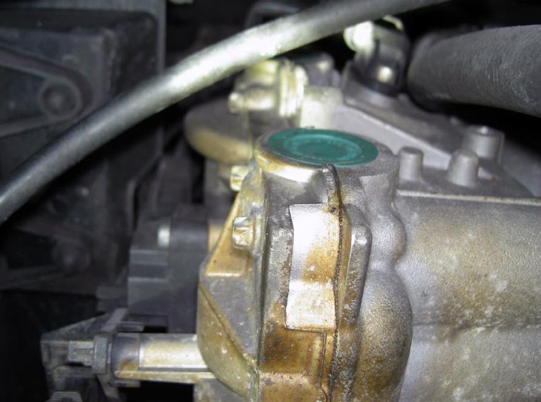
Remove the cam locking key and lightly tap the (supplied) green cam seal in place.

Remove the cam lock and install the seal — photo 1

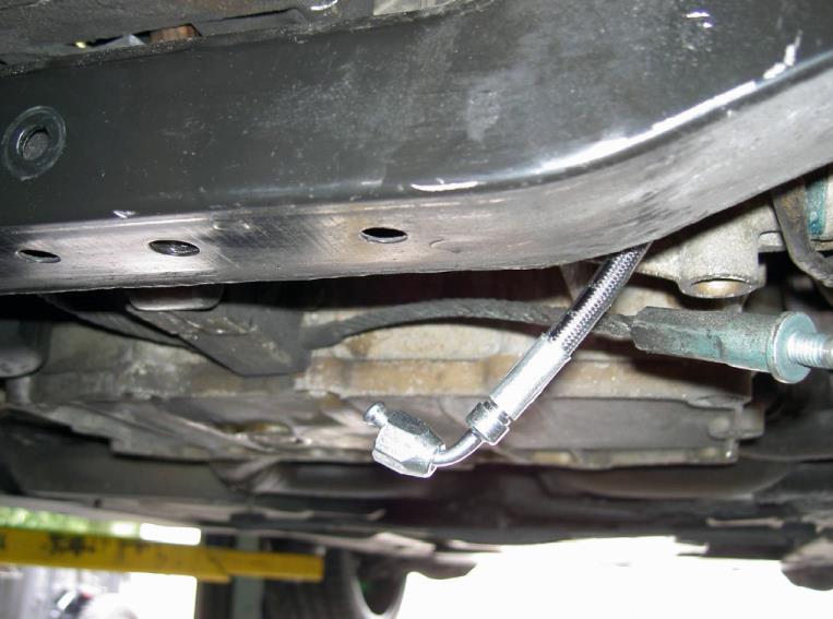
43Step 43Connect the oil line at the DOF flange
From the top of the engine thread the angled end of the high pressure oil line down to the DOF and thread into place.

Torque to 13 Nm (10 lb-ft or 115 lb-in).
Connect the oil line at the DOF flange — photo 1

Connect the oil line at the DOF flange — photo 2

Connect the oil line at the DOF flange — photo 3

44Step 44Reinstall the safety cable or sway bar
On Boxsters replace the earlier removed engine safety cable to the engine support yolk and tighten. In the case of the Carrera, replace the rear sway bar and tighten.

NOTE: If you see the sway bar too close to the DOF fitting, this is an indicator that the motor mounts are worn and need to be replaced.

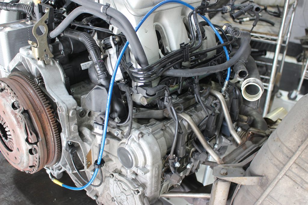
The two photos below show the DOF hose routing from the flange to the port on the cam cover.

Reinstall the safety cable or sway bar — photo 1

Reinstall the safety cable or sway bar — photo 2

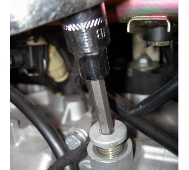
45Step 45Remove the oil port plug
Working from the top of the engine, remove the factory oil port plug on the left side of the top of the engine cam cover, next to the air filter box and under the rear end of the fuel injector bar (on the Boxster). The Carrera’s oil port will be on the front left side of the engine. If there is a sensor in this location, then use the port on the opposite side of the engine.

Remove the oil port plug — photo 1

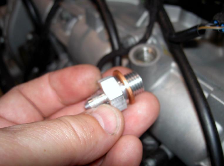
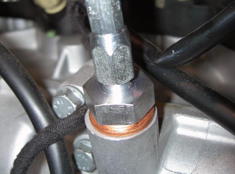
46Step 46Install the oil port adapter
Place the copper crush ring onto the 14 mm end of the hose adapter. The adapter should have already come with the crush washer installed to it (if not, ensure it is properly installed). Put a couple of drops of thread locker (supplied) and thread onto the engine.

Torque to 15 Nm (11 lb-ft or 132 lb-in).

Install the oil port adapter — photo 1

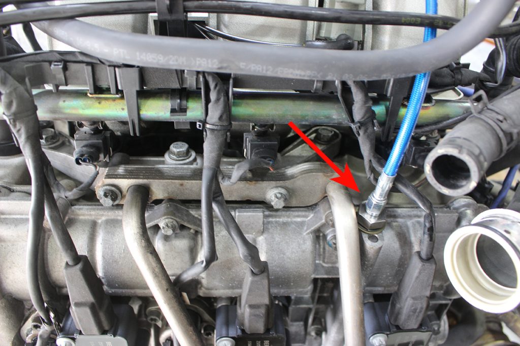
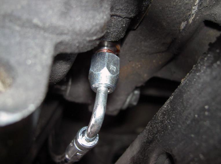
47Step 47Connect the oil line at the engine
Finally thread the free end of the high pressure oil line onto the newly inserted adapter.

Torque to 13 Nm (10 lb-ft or 115 lb-in).
Connect the oil line at the engine — photo 1

Connect the oil line at the engine — photo 2

48Step 48Check for loose components
Check to make sure that nothing is loose.
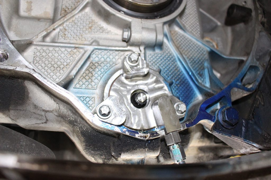
49Step 49Replace the rear main seal if required
If the Rear Main Seal is to be replaced, do it now. Follow the proper Porsche removal & insertion procedures for the rear main seal.

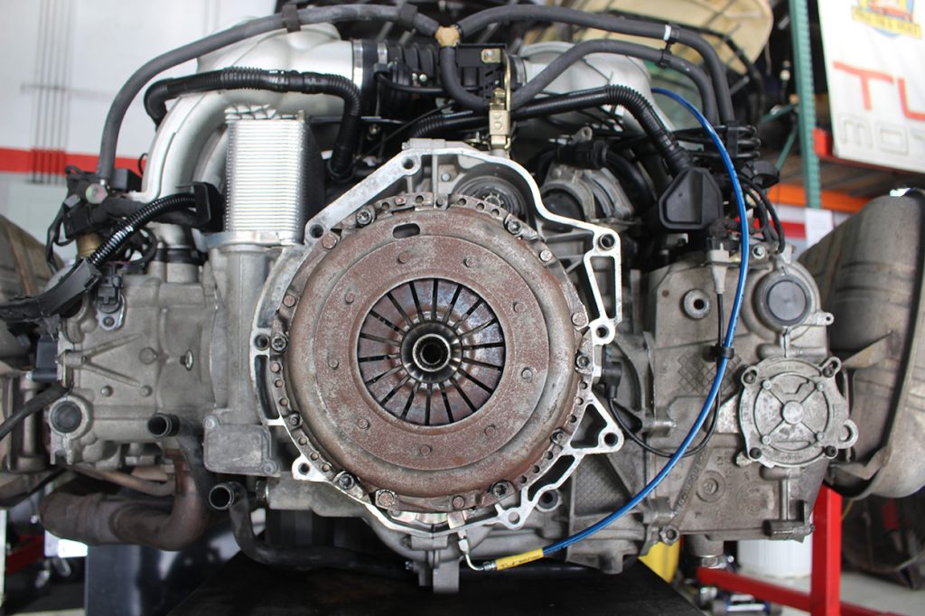
This is how your DOF kit should look installed once you have everything tightened up before installing the flywheel/torque converter/clutch/transmission.
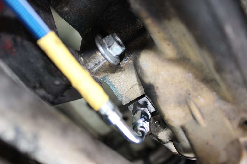
Replace the rear main seal if required — photo 1

Replace the rear main seal if required — photo 2

Replace the rear main seal if required — photo 3

Replace the rear main seal if required — photo 4

50Step 50Reinstall the flywheel
Reinstall the dual-mass flywheel.
51Step 51Reinstall the clutch or torque converter
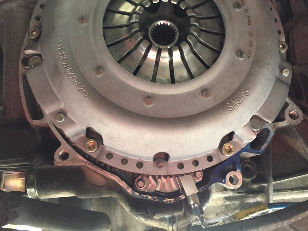
Reinstall the Clutch/Torque Converter.

Reinstall the clutch or torque converter — photo 1

52Step 52Reinstall the transmission
Reinstall the Transmission.
53Step 53Reinstall the remaining components
Reinstall all removed panels, plates, muffler etc.
54Step 54Install the oil filter and refill oil
Install new engine oil filter and fill engine oil level with proper oil.
55Step 55Run the engine and check for leaks
Run the engine and make sure there are no leaks.
56Step 56Complete the installation
Go out and enjoy your Porsche and drive with peace of mind!